Belt Tensioners are great addition to any rig even without having motion implemented. They provide additional level of immersion and a pretty cool modification.
Lot of commercial options are available, but most of them are pretty expensive. Here we will be looking into a DIY approach which also has reasonable cost. It is easy to build and also works quite well.
| The Good: | The Bad: |
|---|---|
| Easy to complete | Noise: High Pitched and Noisy |
| Cheap: 100EUR starting point wihtout Harness | Avoid full lock: it kills servos |
| Requires limited DIY skills | Limited Servo Arm travel: extending not advisable |
| Fast, responsive | High current + supercapacitors |
| Small footprint, very compact, sleek look | |
| Travel: enough to work properly and still protect you from overtensioning | |
| Reliable, low component count |
First lets start with a demo video:
And another video showcasing the complete setup. It features not only the Belt Tensioner but also the Power Supply/Offload circuit box I built for it:
This project is based on Blekenbleu's work documented here: SimHub Custom serial device for Blue Pill
This project utilizes high currency components, 220V power supply and strong robot servos. We do not take responsibility for any injury to yourself or any damage to your equipment. Realizing this project is at your own risk!
Overview:
Project is based around 60KG Robot Servos, controlled from Arduino configured as Custom Serial Device in SimHub. It is relatively easy to assemble, works quite well and cost is moderate (compared to other options).
Robot Servos: Project utilizes 60KG robot servos. They are pretty strong and fast enough for such application. Be careful not to drive them at full lock - they use up lot of juice in full lock and generally can hurt you! They have decent travel (mine are 180 degree) and it is more than enough for a belt tensioner.
Seatbelt: Preferably use 5 or 6-point harness. Four Point Harness is possible but does not work well - when servos pull it on top it just moves around - does not tighten your shoulders. Harness should be fixed from the bottom of the buckle so it remains static and actually have the compression effect - thus at least 5 point.
Supercapacitors: They are optional but recommended part. They smooth out the servo response by profividng constant current. Servos operate faster and quieter with the supercaps
Power Supply: Be careful with the PSU - this type of servo is rated at 6.2A on full lock and this is a lot of power. Preferably drive them at 8V, limit is 8.4V without supercaps. More on this topic further down...
There are several options based on complexity and accessories to build this Project:
Basic Setup:
Includes 2x Robot Servos + Arduino controller + PSU. This is the most simple and basic setup, works well enough and does the job. Be careful with the power supply - these servos pull about 3.5-4A on full lock, you will need properly sized PSU.
Supercapacitor Extension:
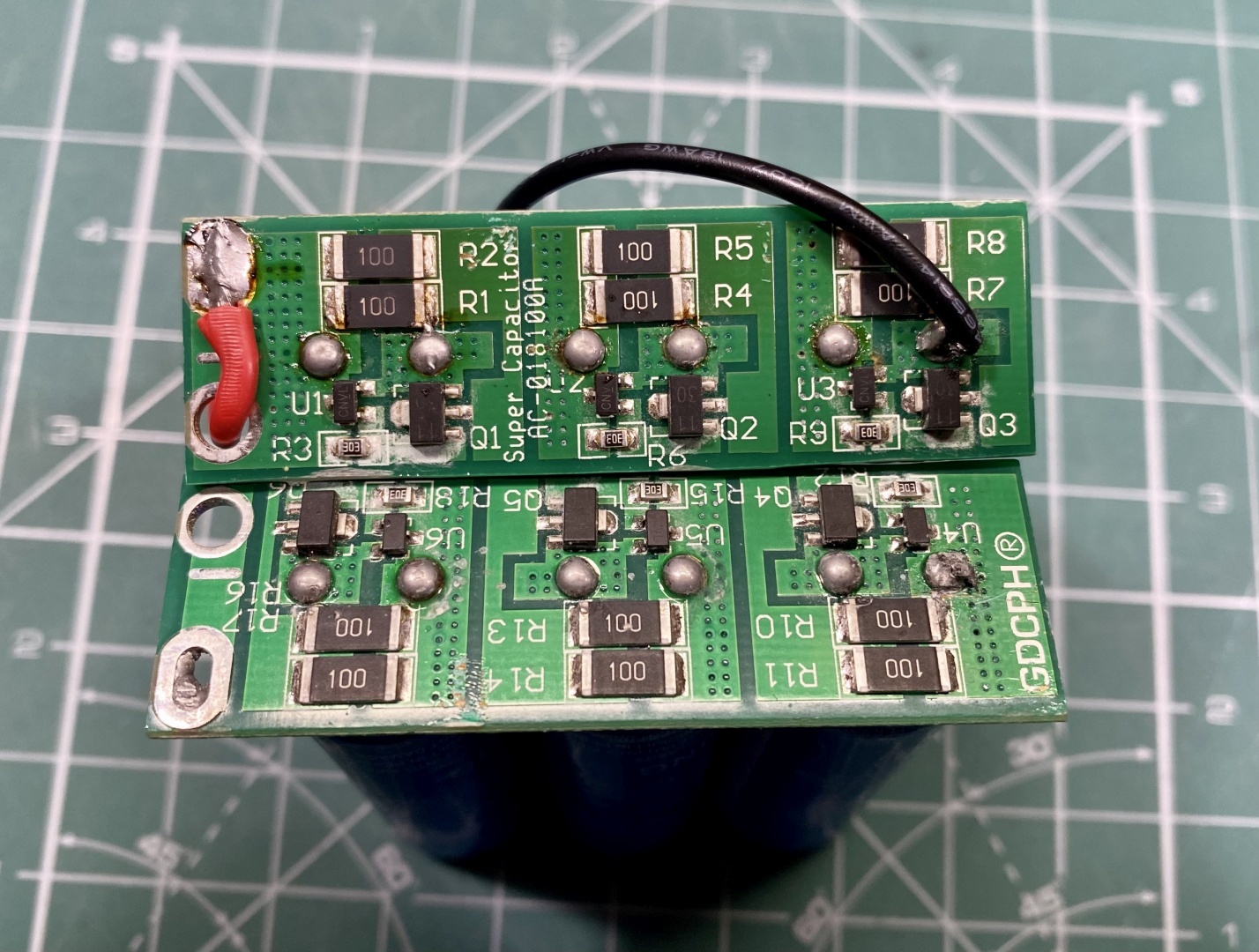
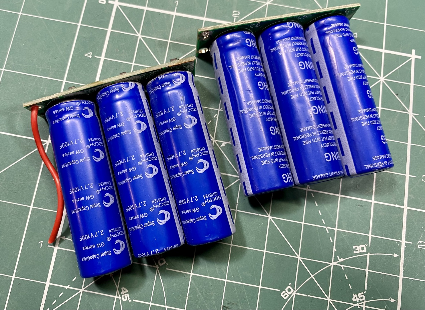
You can add 3x automotive Supercapacitors in series (best approach is to buy pre-soldered component with integrate balancer circuit). The supercaps smoot out servo operation by providing constant power on surges. What you get at the end is smoother, faster and quieter servo operation. This also unloads the PSU by removing the peak drains.
Offload circuit (button or relay operated):
As supercaps store a lot of energy they take considerable amount of time to unload themselves. If no load is connected mine would take up to 10 minutes. As a safety precaution I decided to add and offload circuit. First one was automotive headlight bulb connected in parallel with a switch - when shut down the PSU I switch the circuit on and drain the Supercaps.
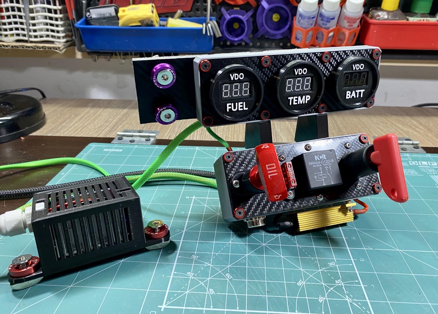
Later extended this with Automotive Blinker Resistor + LED indicator to operate as off-load. I added Automotive Relay to make this switch automated (always wanted to build central console with relay on it). utilizing the relay also decouples galvanically both circuits - when switched off capacitors are connected directly to Offload circuit and PSU is disconnected.
Keep in mind this circuit is not needed, I added it just for precaution and extra satisfaction.
Parts List
- 1. Robot servos 2x, 60KG, 180deg - preferably buy the ones with metal bracket. Do not bother with weaker servos - they burn fast.
- 2. Seat belt - 5 or 6-point harness, 4 does not work well
- 3. Arduino Nano/Pro Micro - maybe others work but I have not tested them
- 4. Super Capacitor High Current 2.7V 100F, 16V 16.6F - cheapest and easiest option is to buy Double Row 6 piece capacitor assembly and cut it in half. These capacitors require ballance circuit for charging and this would be the easiest option to go for.
- 5. DC-DC Buck Converter Step Down Module - I used 300W, 20A peak (15A constant) - needed to step down to 8V
- 6. Power Supply - 12V are the most common and accessible units. I am using 24V as it is also powering my Bass Shakers. Be sure to have adequate current rating.
- 7. Additional parts - automotive fuse and holder (10A), power switch by choice, connectors, cables, digital voltmeter
- 8. Offload circuit - automotive relay if you wish it automated, automotive blinker resistor (1-2.5 OhM), indicator light (LED) by choice
3D Printed Parts
- 1. Seat Belt rollers - ball bearing, remove friction in belts to provide much better experience
- 2. Enclosure for the Step Down Buck Convertor
- 3. Enclosure for supercaps/arduino
- 4. PSU Control Unit for additional extras you want (offload circuit, relay, etc.)
Software
- 1. Arduino Pro Micro + modified SimHub Arduino Sketch - Servo Belt Tensioner on GitHub
- 2. Original BluePill Arduino Sketch if preferred - Blekenbleu on GitHub
- 3. SimHub - Official SimHub Page
Power Considerations
- 1. Servos are rated 6.2A at full lock. I measured mine on Full-Lock at about 4A (ranging from 3.8-4.2A). On "Normal-Lock" (meaning my shoulders do not huirt) it consumes about 2.2A. Stil times 2 both servos will consume almost 5A continuous
- 2. Servos are rated at 8.4V, but Supercaps are 2.7V each - total 8.1V for the three of them. Operationg them at about 8 ensures good performance/longevity balance
- 3. If you cannot find direct PSU at 8 V you will have to add the Step Down DC-DC module
- 4. Servo cables look thin but they are not. For the rest of the circuit I used 16AWG and 18AWG wire (compute PSU grade). You will be powering two servos at about 8V 5A constant at times - be careful with cabling!
- 5. If you add the supercaps you can get away with lower rated StepDown (6A should be fine). If you skip supercaps opt for at least 8A Step down.
- 6. With SuperCaps you can limit your StepDown to 4-5A if it supports it for safety. Without Supercaps this will underpower the servos so use proper rating StepDown.
- 7. Use proper 12V PSU. With Supercaps 5A at 12V should be enough. Without supercaps you need full power realtime, this translates to 5.33A - go for at least 6A 12V PSU
Price Estimate
All these prices are current at the time of writing the article. They are calculated with shipping in Europe. Aliexpress links constantly change and are hard to maintina but searching by component name shoudl give you the part.
| Core Components | Supplier | Price | Count | Total |
|---|---|---|---|---|
| Robot Servo 60KG, 180DEG, Metal Bracket | AliExpress | 33.36 EUR | 2 | 66.72 EUR |
| Arduino Pro Micro | AliExpress | 4.52 EUR | 1 | 4.52 EUR |
| 5-Point Harness | Race-Shop.com | 56.20 EUR | 1 | 56.20 EUR |
| DC-DC Buck Converter Step Down Module 300W 20A | AliExpress | 4.85 EUR | 1 | 4.85 EUR |
| LED Power Supply adapter 12V 5A minimum with SuperCaps, 8A without | AliExpress | 13.78 EUR | 1 | 13.78 EUR |
| Electrical Wire Black-Red - 18AWGx2 (0.75x2), 5m | AliExpress | 3.63 EUR | 1 | 3.63 EUR |
| Illuminated Led Toggle Switch With Safety Aircraft Flip Up Cover Guard 12V20A | AliExpress | 1.79 EUR | 1 | 1.79 EUR |
| Car Blade Fuse with Holder 10A | AliExpress | 0.71 EUR | 1 | 0.71 EUR |
| SubTotal | 152 EUR | |||
| Extended Circuit | Supplier | Price | Count | Total |
| Super Capacitor High Current 2.7V 100F Double Row 6pcs 16V 16.6F | AliExpress | 18.19 EUR | 1 | 18.19 EUR |
| Aluminum Power Metal Shell Case Wirewound Resistor 50W-1R | AliExpress | 1.07 EUR | 1 | 1.07 EUR |
| Automotive Relay JD1914 12V 40A 5p | AliExpress | 2.2 EUR | 1 | 2.2 EUR |
| 6mm LED Waterproof Metal Indicator Light Signal Lamp 12V | AliExpress | 0.75 EUR | 1 | 0.75 EUR |
| SubTotal | 22 EUR | |||
| Total | 174 EUR |
Electronic Schematics
Basic Configuration Schematics
Here we have only the basics: 12V PSU + DC-DC StepDown + both servos + Arduino + Supercaps. If you opt out of supercaps just remove their leg from the schematics (also the car fuse should be connected accordingly or removed):
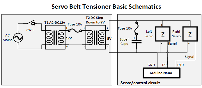
Basic Configuration Wiring Diagram
Below is simplified wiring diagram how to connect the basic circuit + Supercaps. It is pretty straightforward, should be easily reproducable. Yet again - Be Careful! This is high current circuit with supercaps in it!
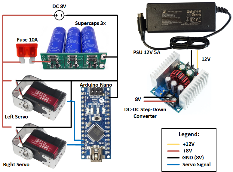
Extended Configuration Schematics
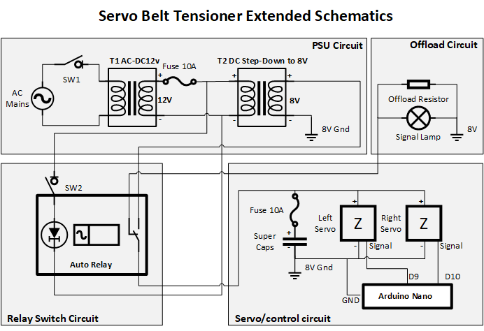
Here we have added the offload resistor circuit + signal light. This is controlled with automotive relay but it can be changed to simple switch for manual operation.
Keep in mind that DC-DC converter works as step up the other way. When power is cut the DC-DC converter feeds 12V back upstream and if your relay keeps the control circuit engaged for wide voltage range much below 12V it will have big delay.
Adding diode in the circuit will rectify this but keep in mind - this diode should be high power as we have up to 8A! Attempting the advanced circuit will require some basic electrotechnics knowledge!
Assembly instructions
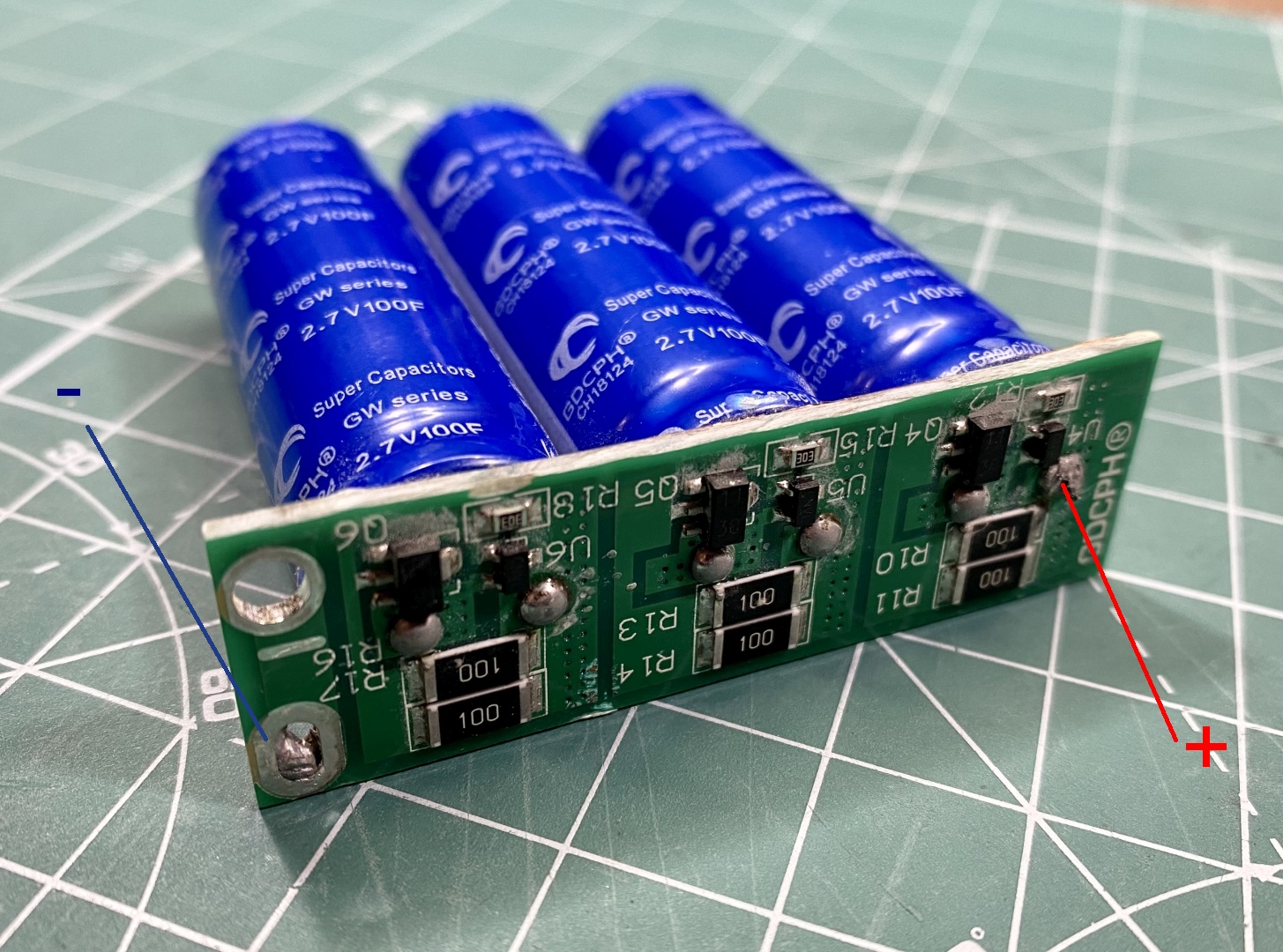
Cutting the SuperCaps in Half and Soldering
The supercaps module is easily cut in half. Just make a clean cut in the middle and you will have two modules for your project. I cut mine with a dremel and metal cutting disk:
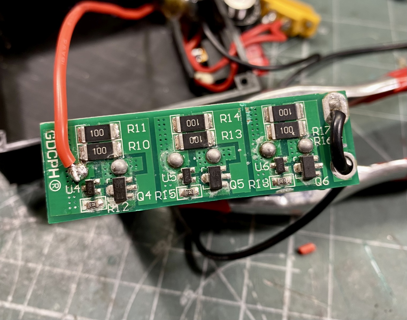
You will use one of the PCB's soldering points (either positive or negative) and the other will be the last capacitors leg furtherst away:
Solder the rest of the basic circuit
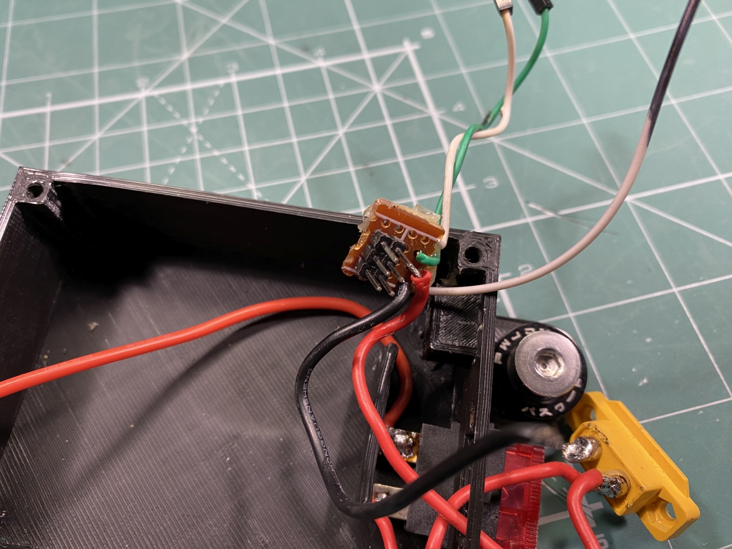
JST 2.54mm headers are very comfortable terminals for connecting the servo. You can use small piece of project PCB and solder them there. Supply them with 8V from the supercaps, then you need 3 wires for Ground and Signals to Arduino. The control box has comfortable opening to mount the Servo connectors:
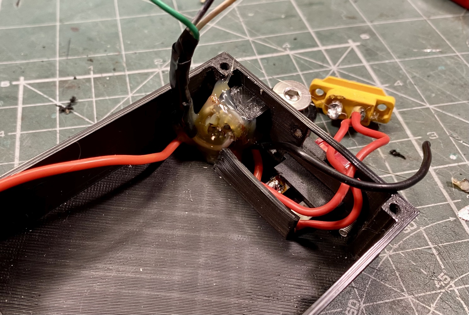
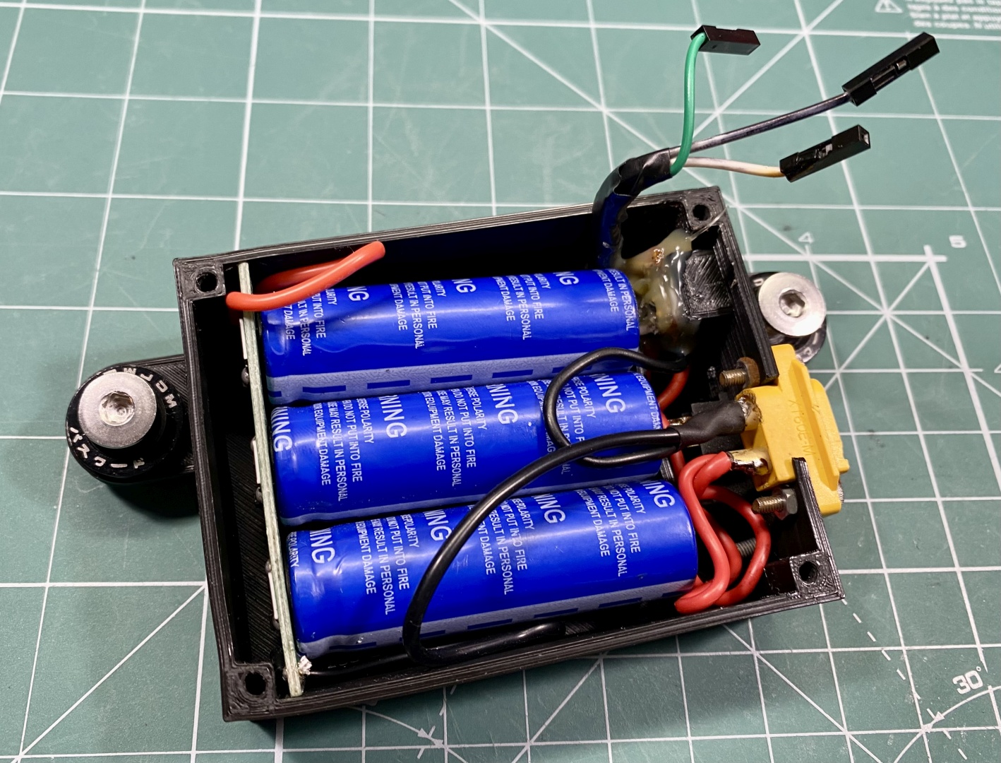
Solder the Supercaps to the appropriate wires. Keep them short but provide enough slack to work comfortably:
Assemble control box
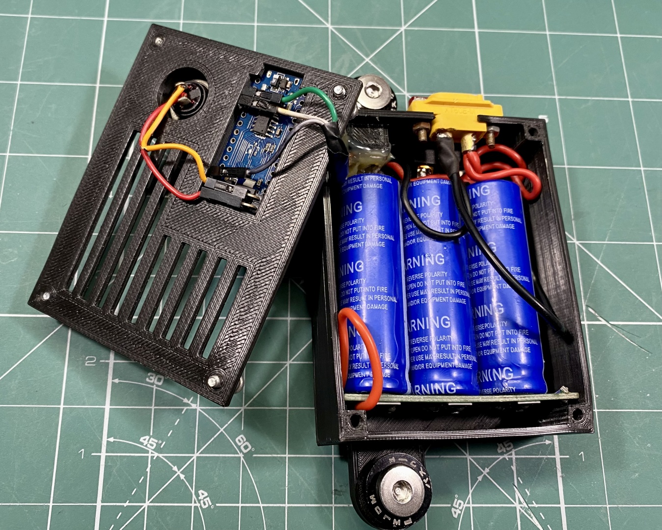
Route all the power cables accordingly and try not to cross them especially with signal wires. Insert SuperCaps in their place, mount Arduino in its place and connect signal wires:
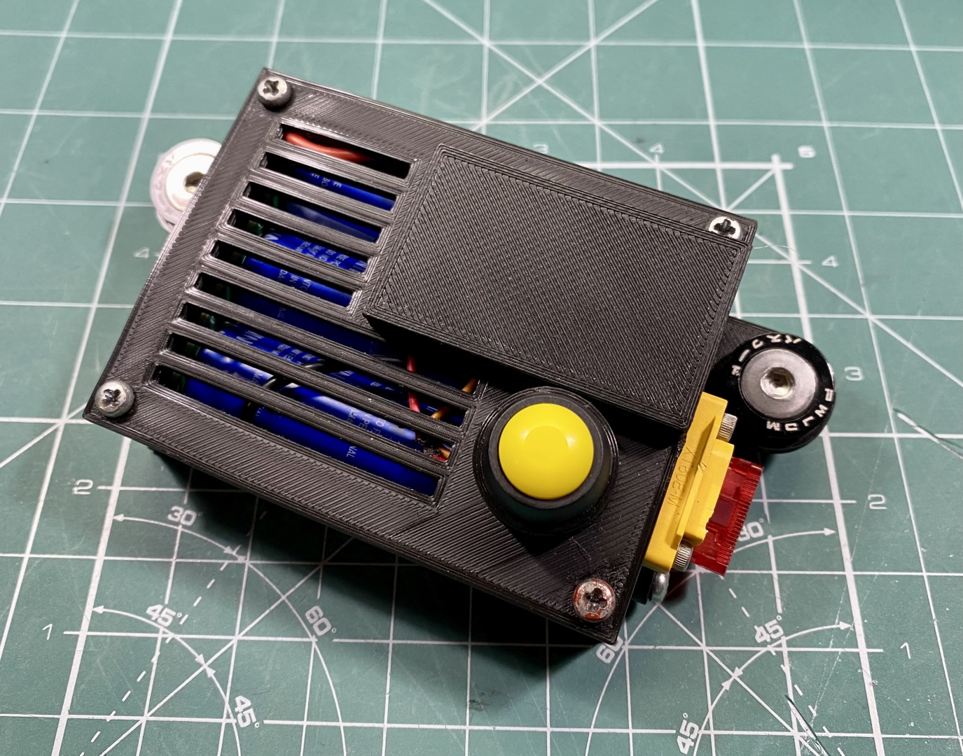
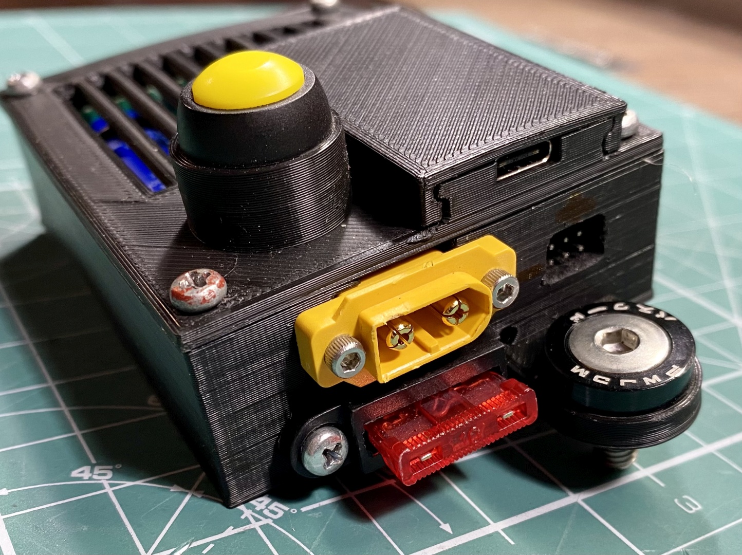
Assemble box with M3 screws and your're done:
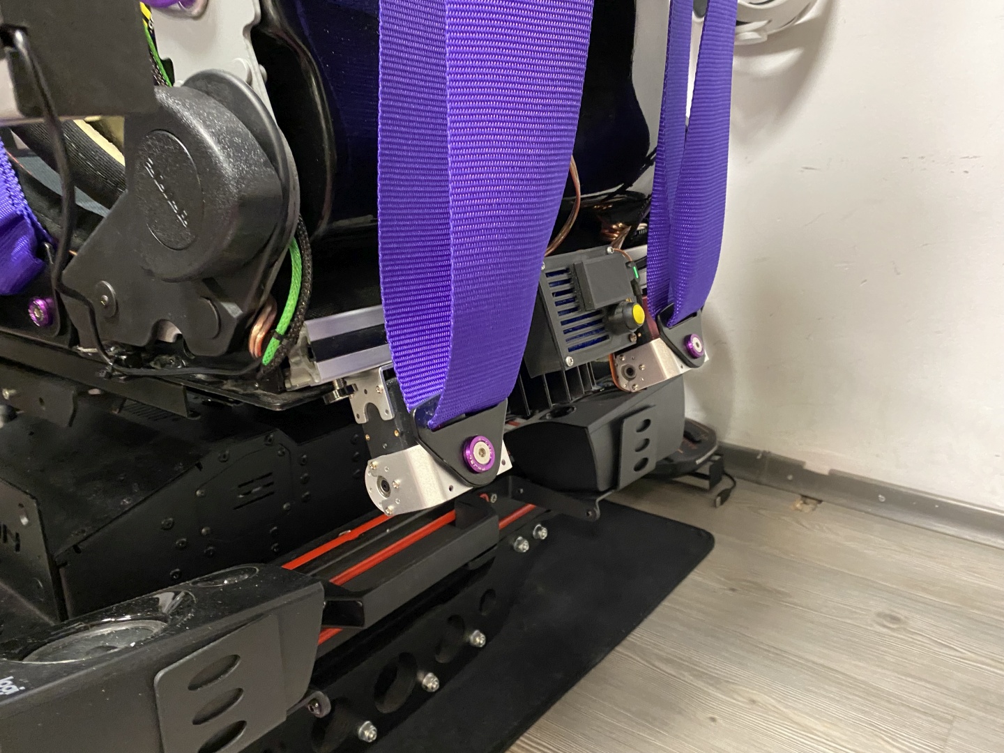
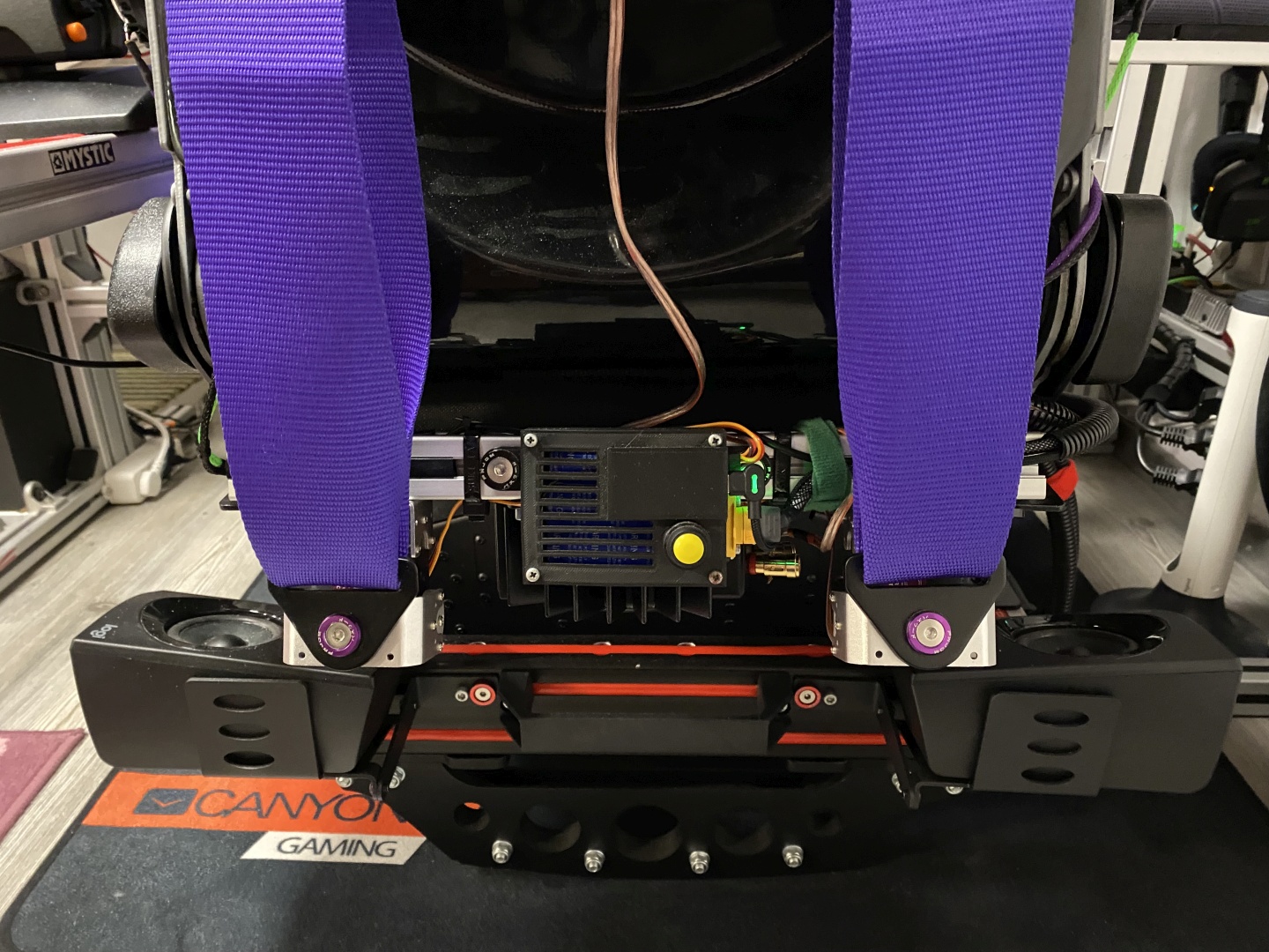
Mounting the servos
Use the supplied brackets and mount the servos to a suitable place. If you have seatmover mount them to seat itself. Connect to computer after software installation so servos zero out in neutral postition. Check servo travel direction.
After you identified zero position and verified travel direction it is safe to attach the moving brackets. After that attach seatbelts:
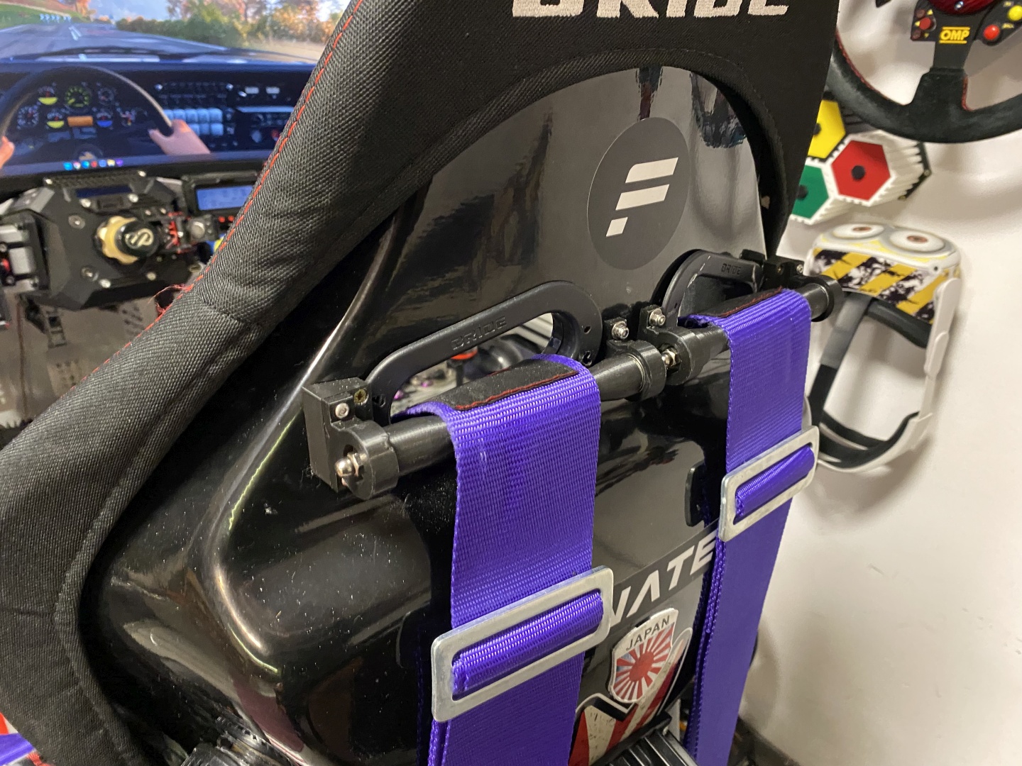
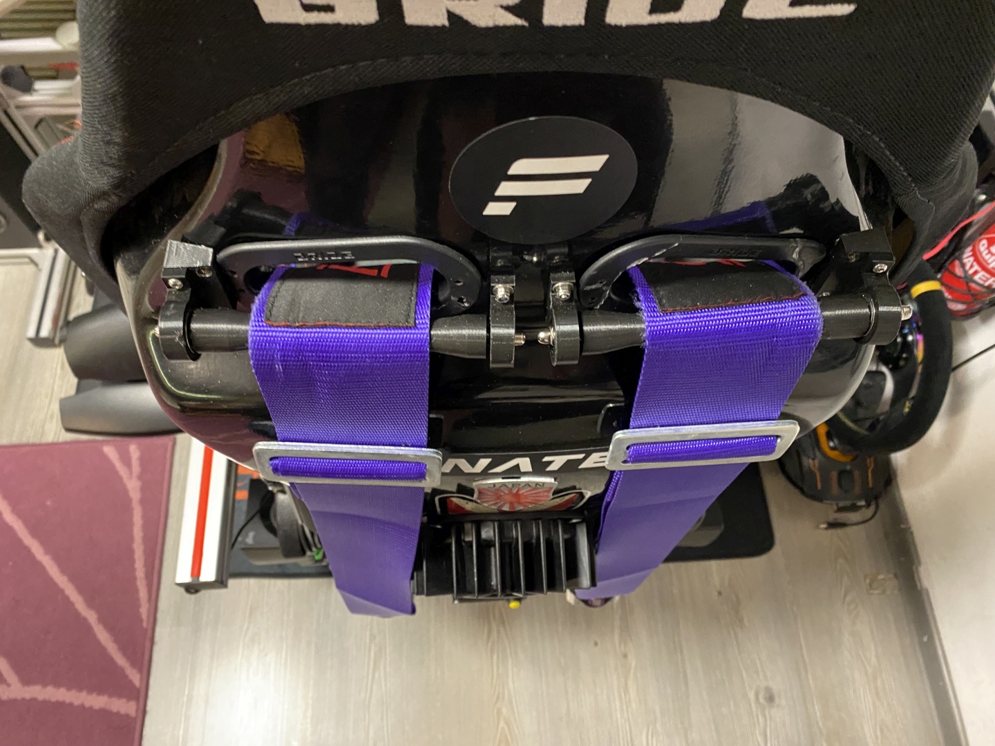
Belt Rollers
Belt Rollers are advisable upgrade to the Tensioner. They ensure smooth travel for the harness, also guide it properly so it tensions your shoulders backwards rather than pulling them straight down:
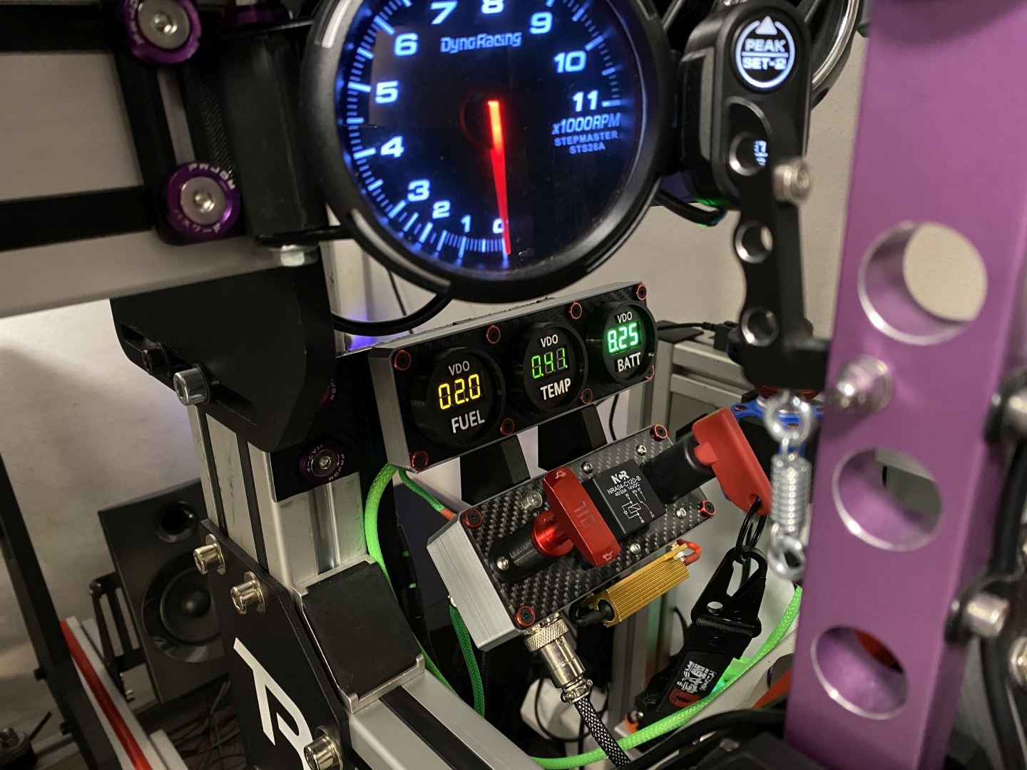
Fancy control enclosures and offload circuit
All of the below are linked up in the article so if you like them you can build them. The Offload circuit contorl box is part of my modular central console design:
Software configuration
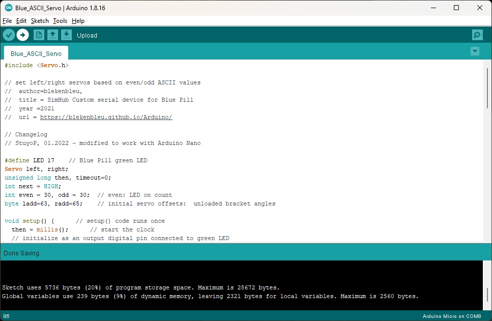
Flash Arduino Sketch
Flashing the Arduino is pretty simple - just download the provided sketch from GitHub and upload it to an Arduino Nano (Pro Micro should work fine as well):
Head on to SimHub Settings->Plugins and enable the Custom Serial Device Plugin:

Custom Serial should appear now as tab in the navigation sidebar. Open it and add New Serial Device:

Next step would be to import the Custom Device Settings with the Import Settings link. Open the .shsds profile file and it should load the below settings for you.
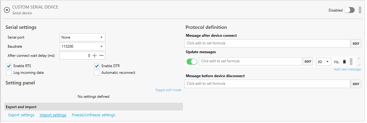
Slecet the correct COM prot from the dropdown (if you are using other Arduinos with SimHub this port automatically will be excluded from standard device list). You can keep the default proposed baud rate of 115200, I set 9600 to debug some issues and as it was working OK I presume I left it like this:
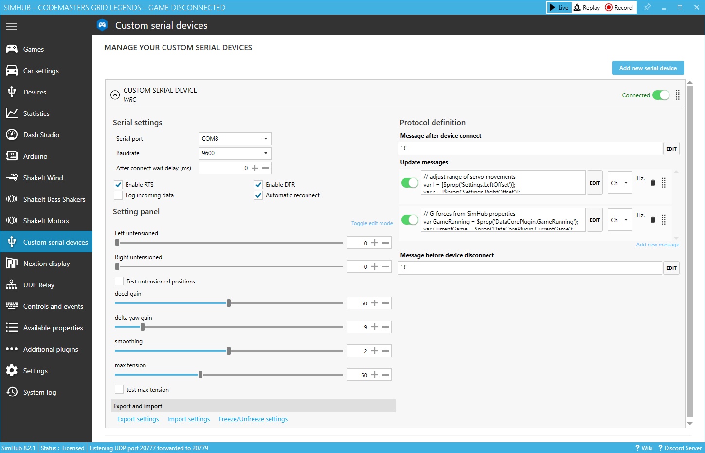
Untensioned Sliders: When you first connect the servos they will go to their Zero position. At this point you cna adjust the brackets to your actual desired untensioned setting. Alternatively you can use the two sliders to adjust on the fly. this also was taken into accound in the Arduino code.
Test untensioned positions: Send commnad to put servos in untensioned position. As both custom Program and Arduino code are currenlt set to use servo Zero position this should not have effect.
Decel gain: This adjust the severity of the braking effect.
Delta yaw gain: This is the turning effect - controls how much the inside belt is released/outside tensioned in turns.
Smoothing: Smoothing - this interpolates the input so you get smooth consistent effect instead of constant servo jerking.
Max tension: Set the max angle at which servos stop their rotation. At 65KG this servos are very strong and I highly doubt you will use them at full lock before reaching max angle (at full lock they really hurt my shoulders). Also full lock should be avoided as it can kill the servos + it draws too high current.
Conclusion
Robot/Hobby Servo based Sim Racing Belt Tensioner is very easy project to complete and requires very limited DIY skills. Furthermore at about 100EUR starting point (harness not included) thie easily is the cheapest possible Active Seatbelt Tensioner you can find. With Supercapacitors it providees fast and smooth response, strogner than you will ever need and 65KG servos appear to be quite reliable - mine is under heavy load for past year and still works flawless. On top of that servos are small, light and easy to integrate anywhere (even on a seat mover). The only real concern is noise - hobby servos have high pitch and are relatively noisy. When mounted somewhere far from your seat it could be Ok, but as mine are right below the seat I can hear them even with headphones.
All of the above said - if you are on a lookout to add Active Belt Tensioning to your rig and have very limited resources - look no further. This is great project even if you do not have moition on your setup.

Comments
+5 # jaz2
+1 # NicCf1
0 # SPD
License