Assembly instructions
Cutting the SuperCaps in Half and Soldering
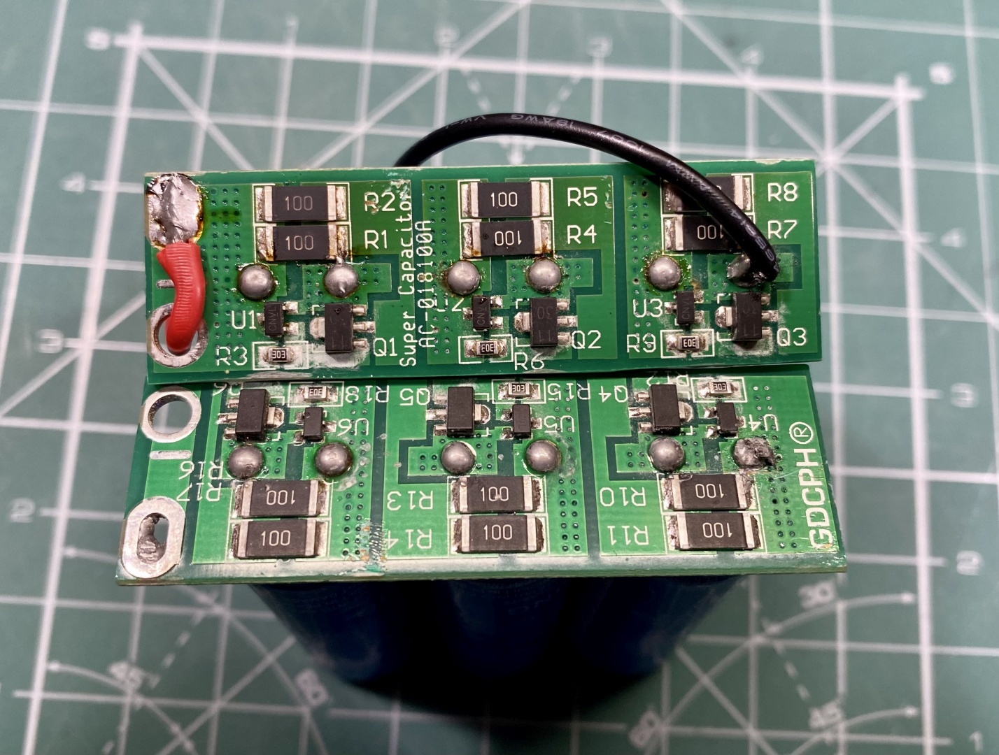
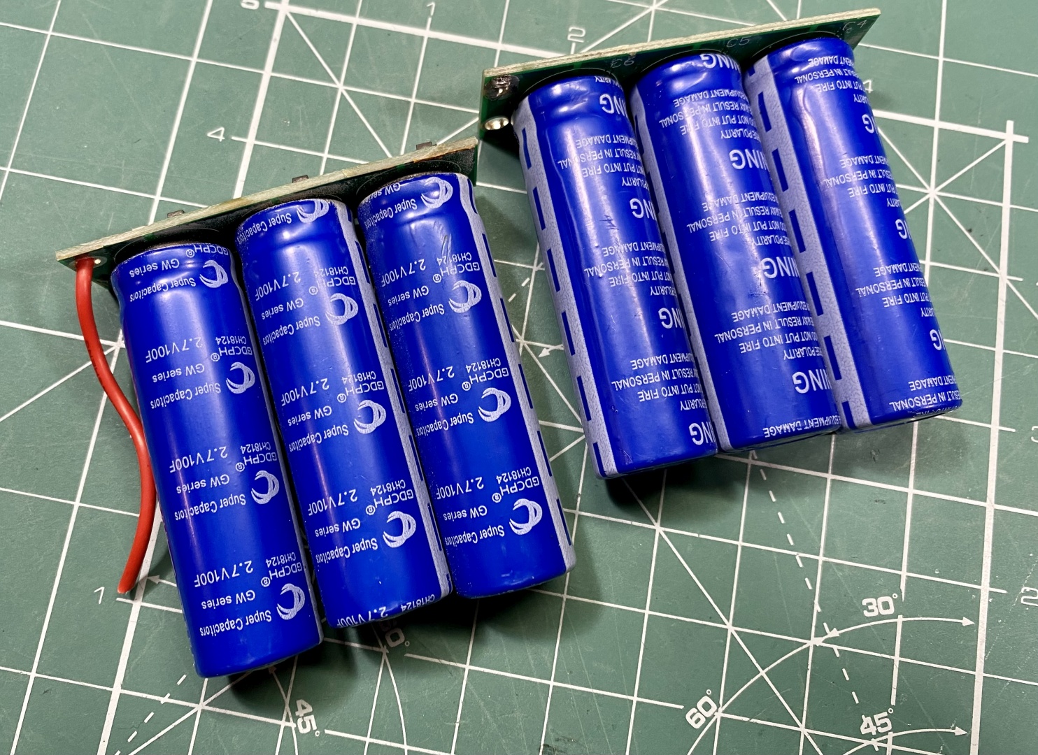
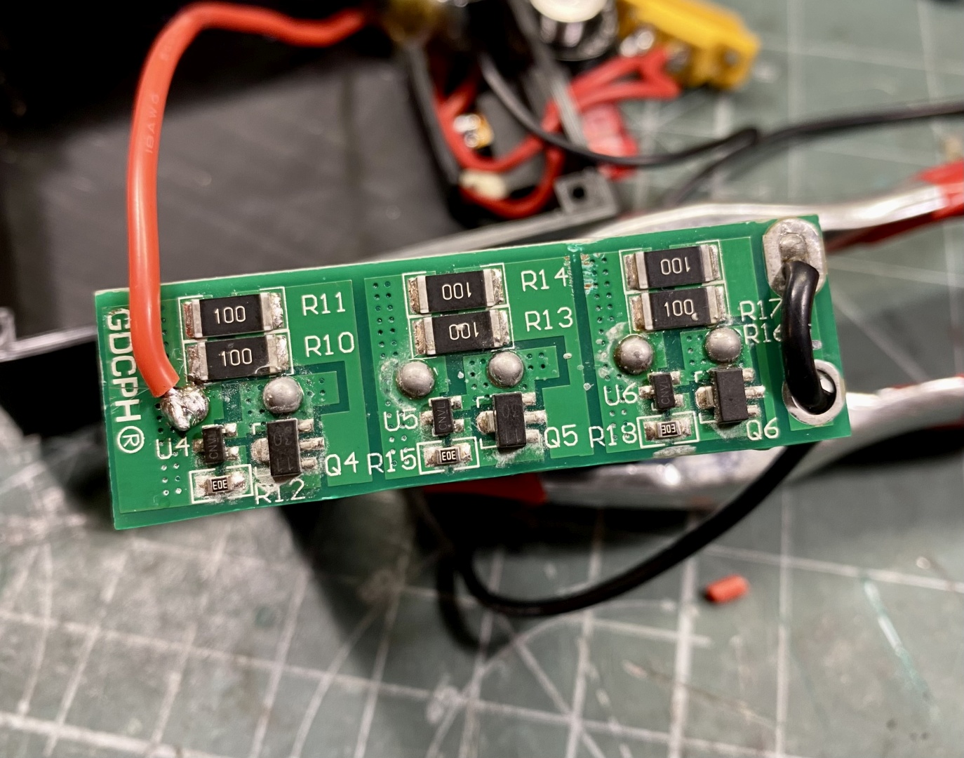
The supercaps module is easily cut in half. Just make a clean cut in the middle and you will have two modules for your project. I cut mine with a dremel and metal cutting disk:
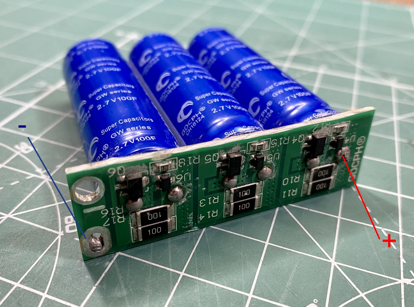
You will use one of the PCB's soldering points (either positive or negative) and the other will be the last capacitors leg furtherst away:
Solder the rest of the basic circuit
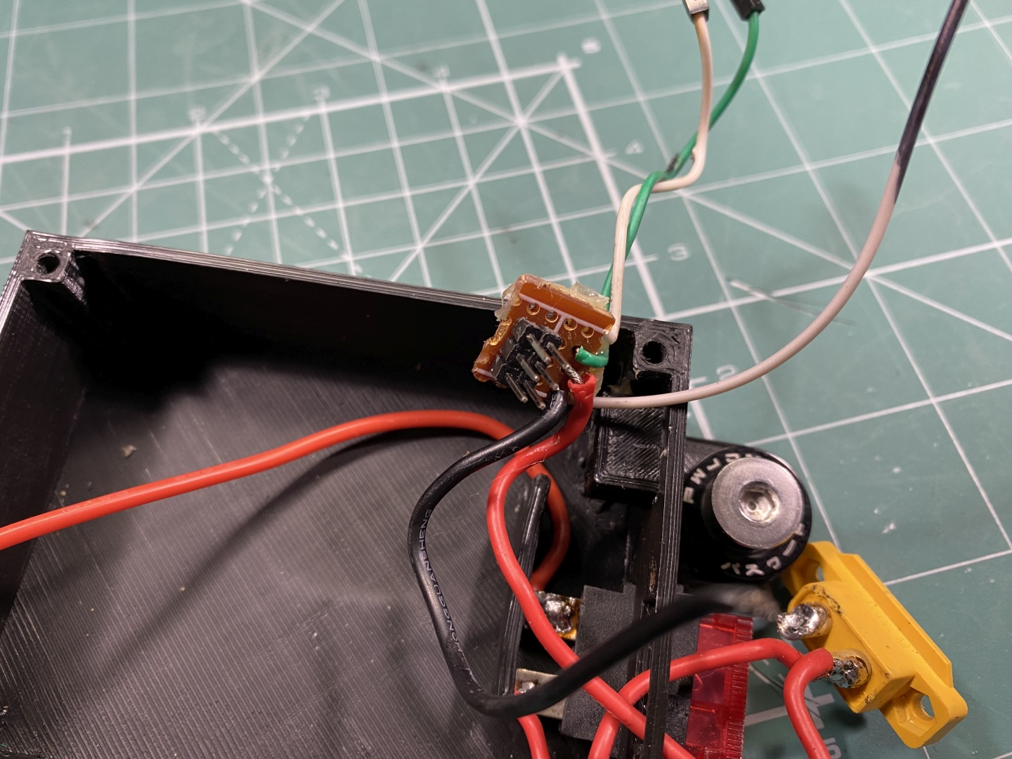
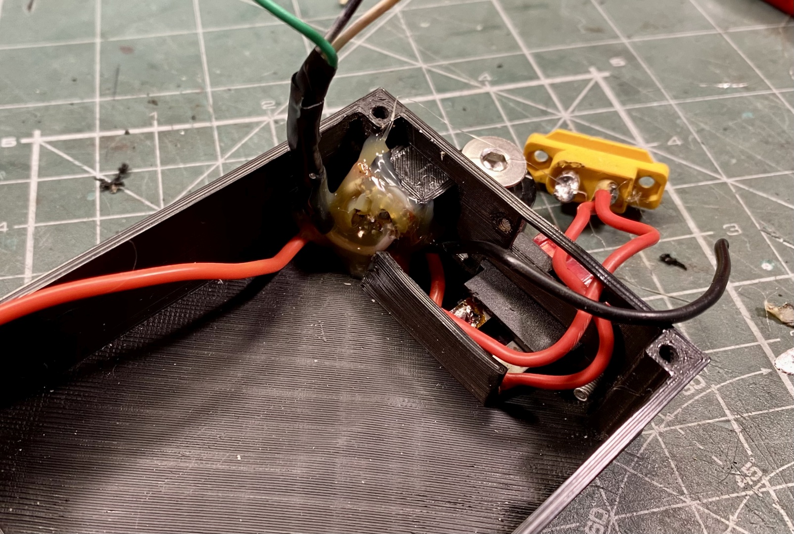
JST 2.54mm headers are very comfortable terminals for connecting the servo. You can use small piece of project PCB and solder them there. Supply them with 8V from the supercaps, then you need 3 wires for Ground and Signals to Arduino. The control box has comfortable opening to mount the Servo connectors:
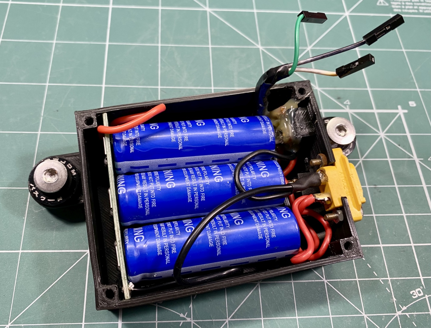
Solder the Supercaps to the appropriate wires. Keep them short but provide enough slack to work comfortably:
Assemble control box
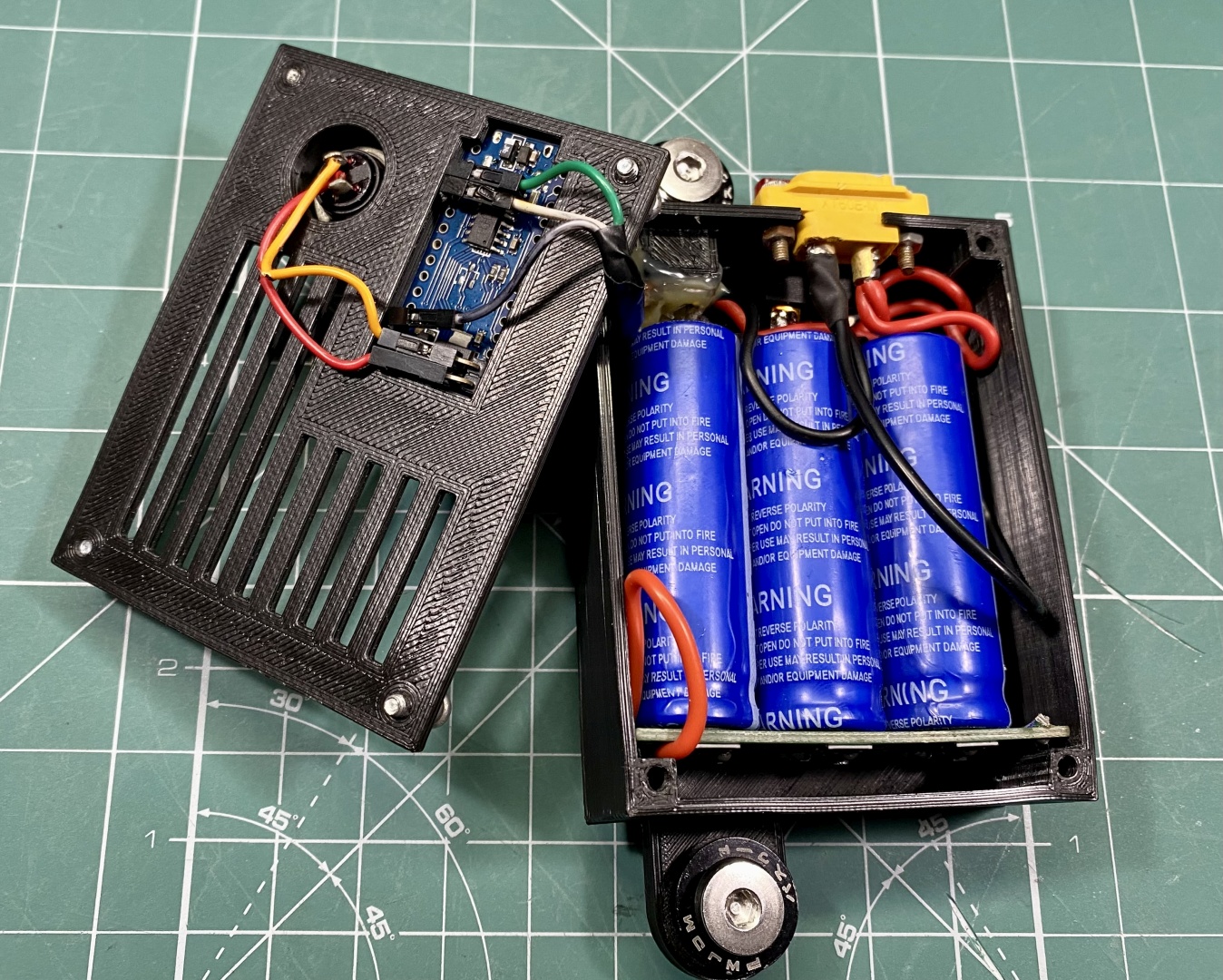
Route all the power cables accordingly and try not to cross them especially with signal wires. Insert SuperCaps in their place, mount Arduino in its place and connect signal wires:
Assemble box with M3 screws and your're done:
Mounting the servos
Use the supplied brackets and mount the servos to a suitable place. If you have seatmover mount them to seat itself. Connect to computer after software installation so servos zero out in neutral postition. Check servo travel direction.
After you identified zero position and verified travel direction it is safe to attach the moving brackets. After that attach seatbelts:
Belt Rollers
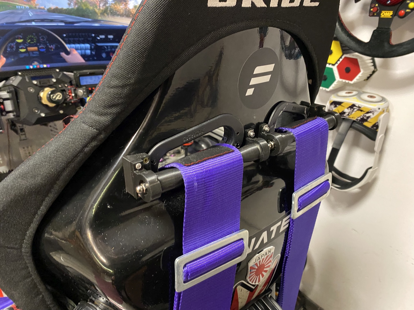
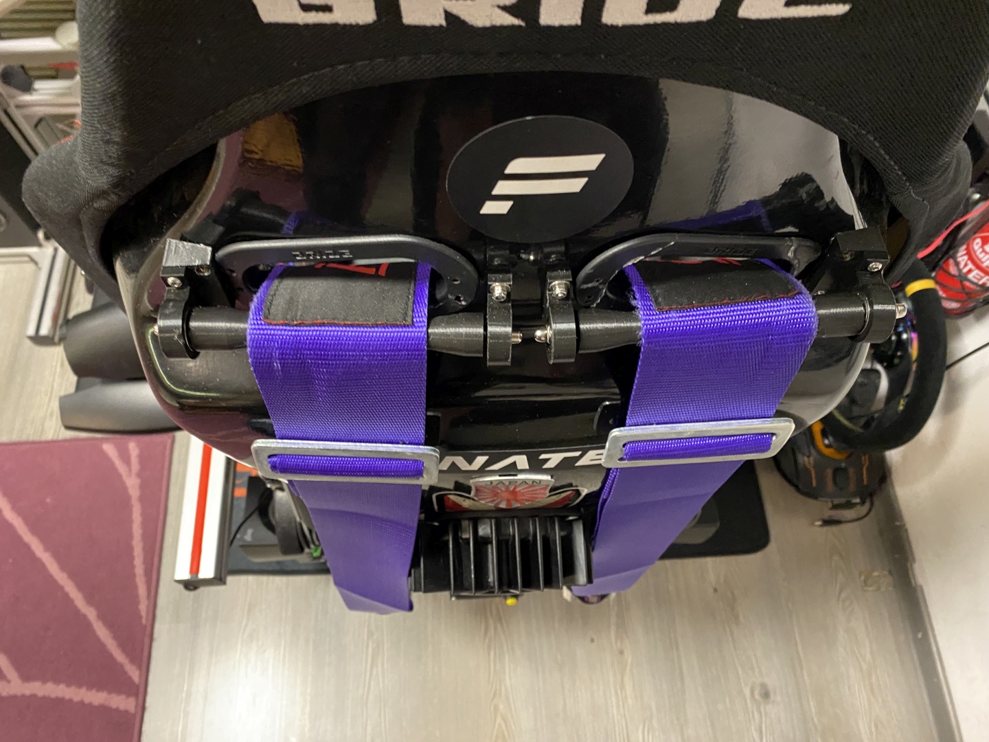
Belt Rollers are advisable upgrade to the Tensioner. They ensure smooth travel for the harness, also guide it properly so it tensions your shoulders backwards rather than pulling them straight down:
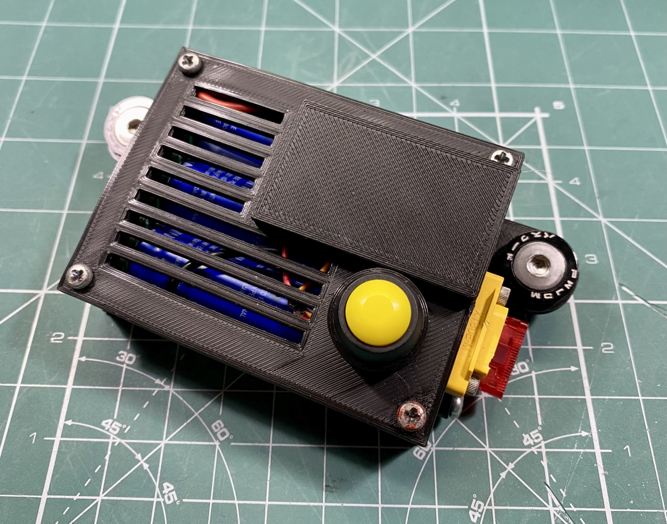
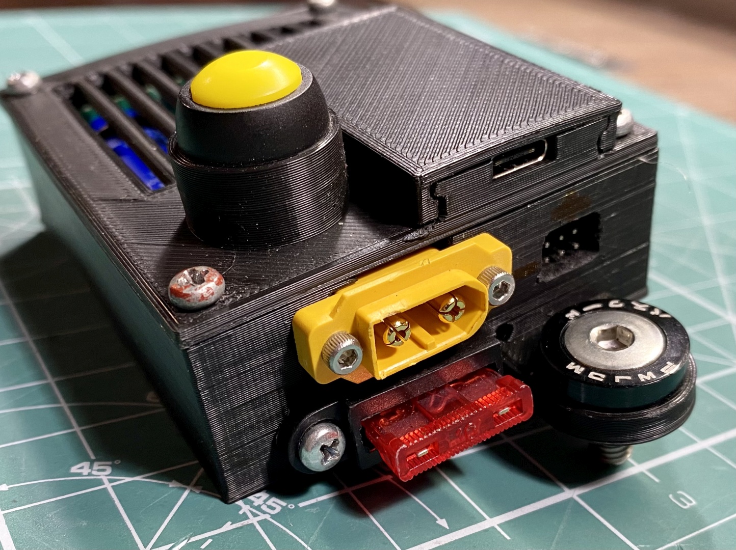
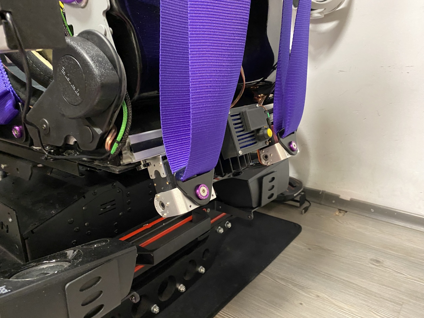
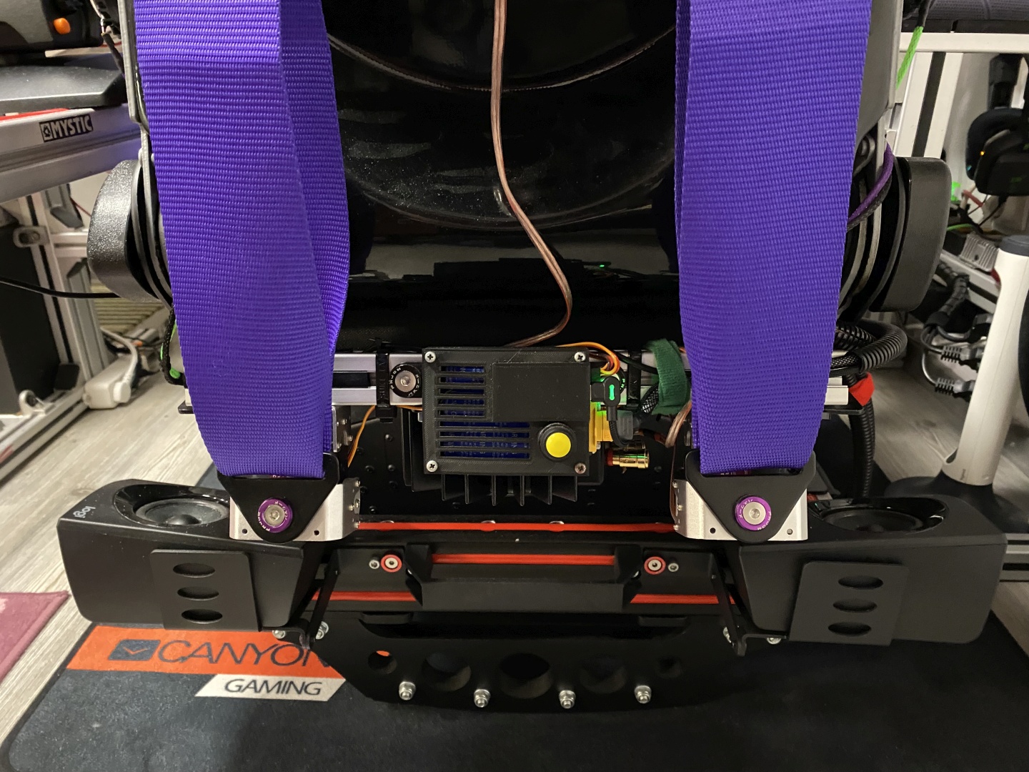
Fancy control enclosures and offload circuit
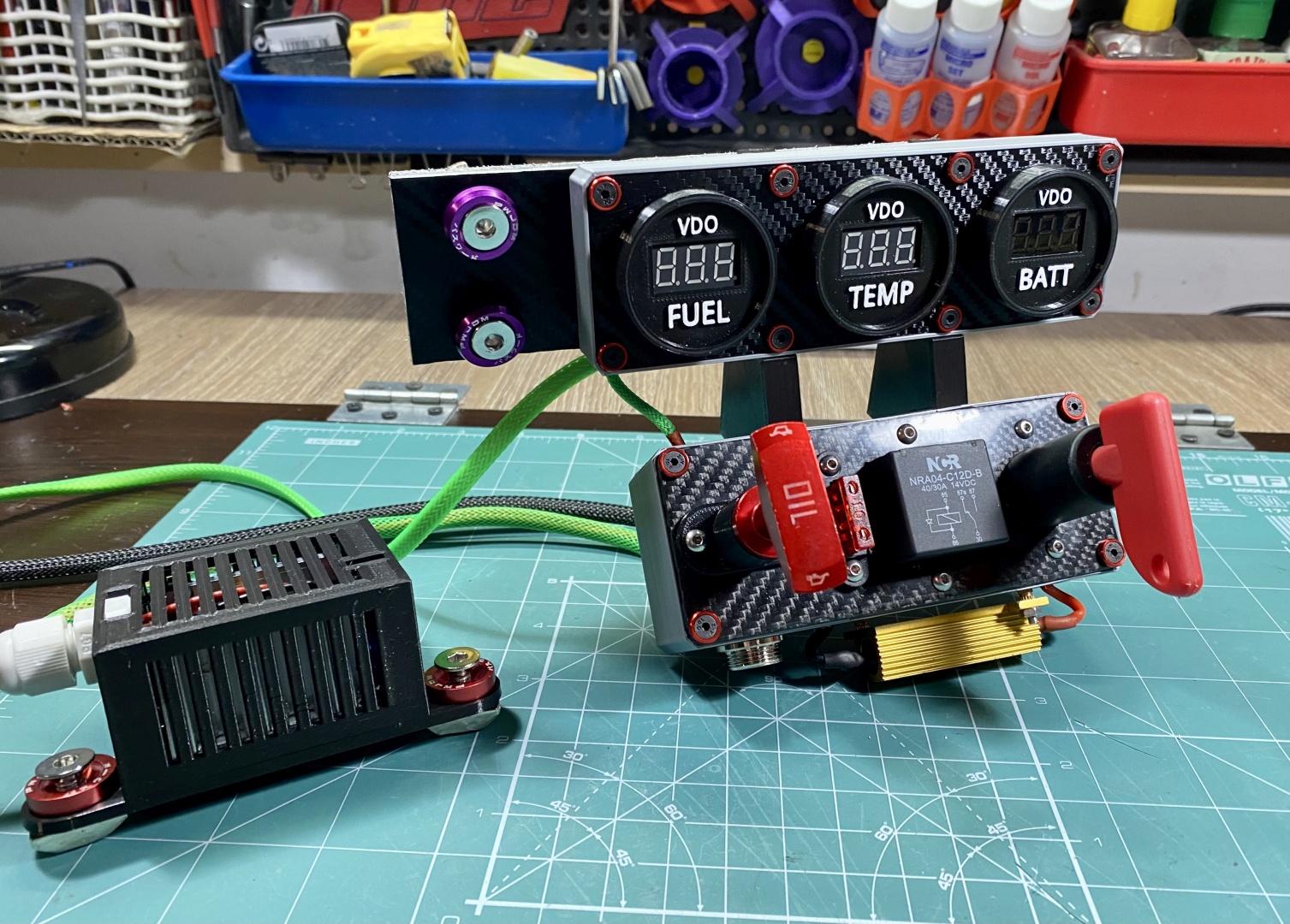
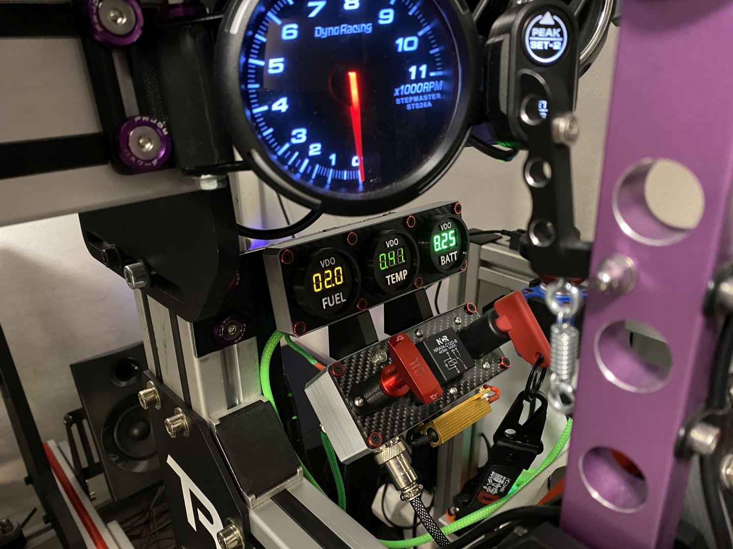
All of the below are linked up in the article so if you like them you can build them. The Offload circuit contorl box is part of my modular central console design:

Comments
+5 # jaz2
+1 # NicCf1
0 # SPD
License