Electronic Schematics
Basic Configuration Schematics
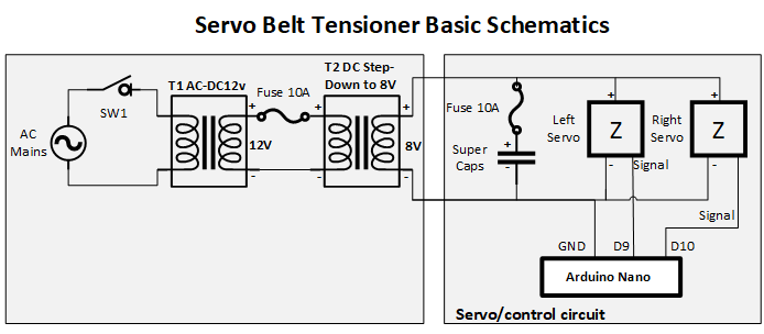
Here we have only the basics: 12V PSU + DC-DC StepDown + both servos + Arduino + Supercaps. If you opt out of supercaps just remove their leg from the schematics (also the car fuse should be connected accordingly or removed):

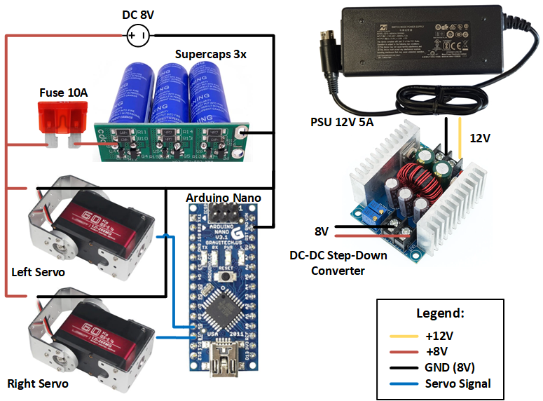
Basic Configuration Wiring Diagram
Below is simplified wiring diagram how to connect the basic circuit + Supercaps. It is pretty straightforward, should be easily reproducable. Yet again - Be Careful! This is high current circuit with supercaps in it!

Extended Configuration Schematics
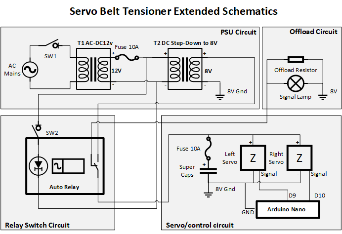
Here we have added the offload resistor circuit + signal light. This is controlled with automotive relay but it can be changed to simple switch for manual operation.
Keep in mind that DC-DC converter works as step up the other way. When power is cut the DC-DC converter feeds 12V back upstream and if your relay keeps the control circuit engaged for wide voltage range much below 12V it will have big delay.
Adding diode in the circuit will rectify this but keep in mind - this diode should be high power as we have up to 8A! Attempting the advanced circuit will require some basic electrotechnics knowledge!


Comments
+5 # jaz2
+1 # NicCf1
0 # SPD
License