Resources
This is advanced DIY project and you will need some PIC programming understanding, specific tools (PIC programmer) and decent soldering skills. Here is what you will need:
- The HEX code from GitHub project page
- PIC Programmer - K150 clone works well
- MicroPro PIC programming software
- PIC flashing knowledge, following links will help:
- Program a PIC 16F690 with the DIY Kit 150 Programmer
- How to Use K150 PIC Programmer Video
- K150 USB PIC Programmer
- K150 USB PIC Programmer Manual
- STLs for open-top mount bracket and full enclosure for 3D Print
Program Code
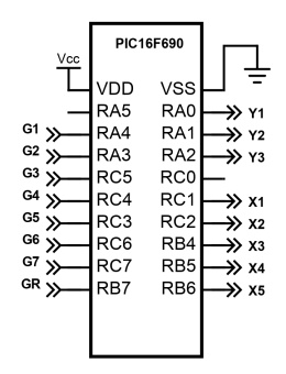
Source prgram code and compiled HEX file for flashing can be found on the Project GitHub Page. Program is very simple, tracks 8 inputs connected to the Shifter Gear Switches and alternates amongst 8 outputs which simulate X and Y Axis Voltage Drops. Gear states are as follows:
- X-Axis has 5 discreet states determining horizontal stick position: Low (R) - Low-Med (1-2) - Medium (3-4) - Med-High (5-6) - High (7).
- Y-Axis has 3 discreet states determining vertical stick position: Low (stick is Up) - Medium (Neutral) - High (stick is Down).
- Neutral - X is Medium, Y is Medium. Program keeps Y2 and X3 outputs engaged when no input is detected.
- 1st Gear - X is Low-Med, Y is Low. Outputs X2 and Y1 are engaged.
- 2nd Gear - X is Low-Med, Y is High. Outputs X2 and Y3 are engaged.
- 3rd Gear - X is Medium, Y is Low. Outputs X3 and Y1 are engaged.
- 4th Gear - X is Medium, Y is High. Outputs X3 and Y3 are engaged.
- 5th Gear - X is Med-High, Y is Low. Outputs X4 and Y1 are engaged.
- 6th Gear - X is Med-High, Y is High. Outputs X4 and Y3 are engaged.
- 7th Gear - X is High, Y is Low. Outputs X5 and Y1 are engaged.
- Reverse Gear - X is Low, Y is Low. Outputs X1 and Y1 are engaged.
Below is the source code and simplified I/O digram displaying how the PIC16F690 gates are configured:

Flashing Firmware
After you install the MicoPro software and downloaded the HEX file it is simple matter of connecting you PIC programmer and flash it to your PIC16F690 microchip. The software will show you the correct position of the PIC in the ZIF (Zero Insertion Force) socket. You will notice that it supports only 14pin PIC16F690s. This is not an issue - you can just bend the bottom most four pins and still place it properly and be able to flash the firmware successfully.
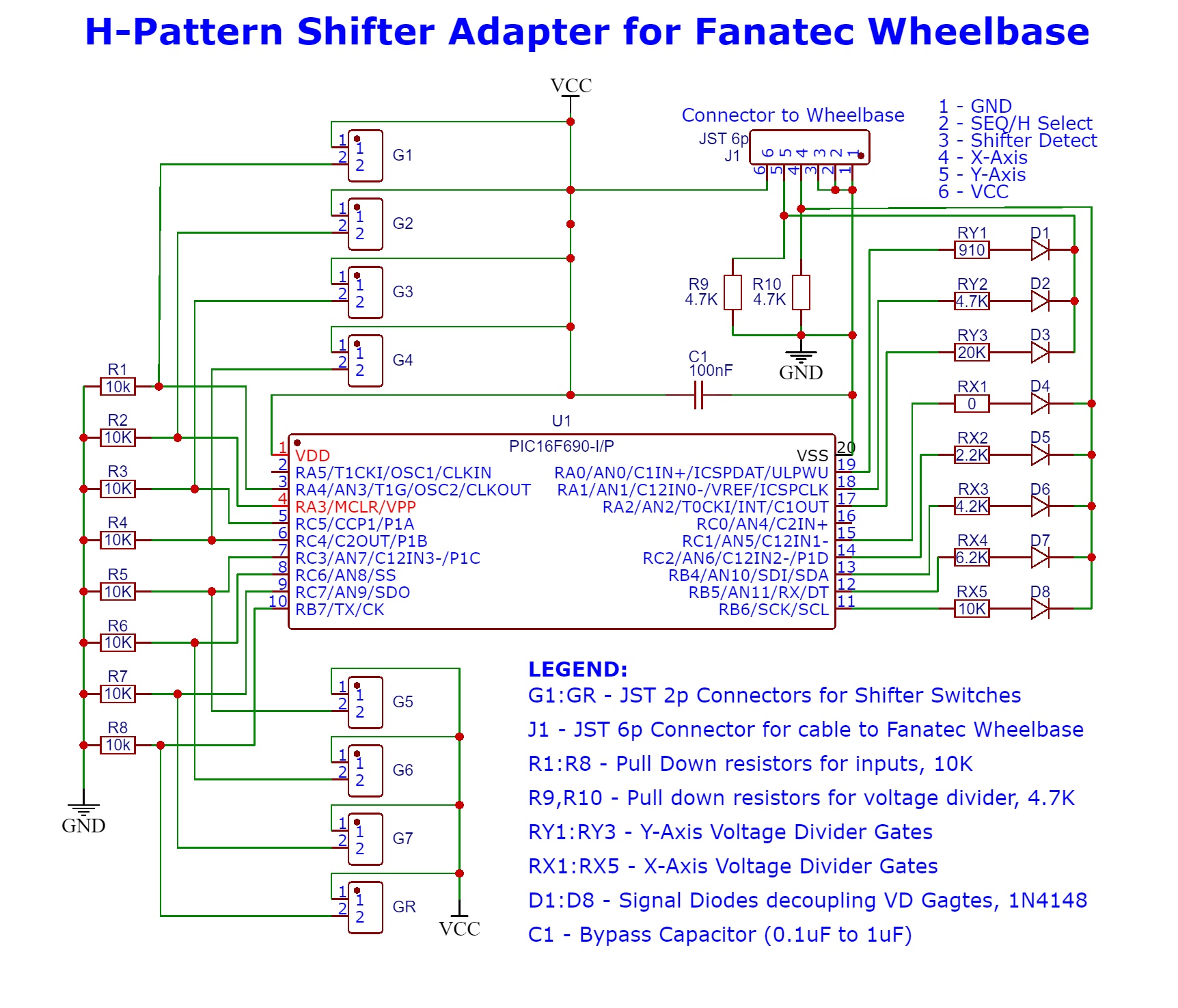
H-Pattern Interface Schematics
All Gear Inputs are pulled down to LOW (GND) and upon switch engaged they are pulled up to HIGH (VCC). Wheelbase X-Axis and Y-Axis pins are pulled down to LOW and upon output from PIC the Voltage Divider circuit is engaged, voltage drop is present on X and Y pins. All outputs are decoupled with Diodes so no feedback is present on PIC I/O pins:
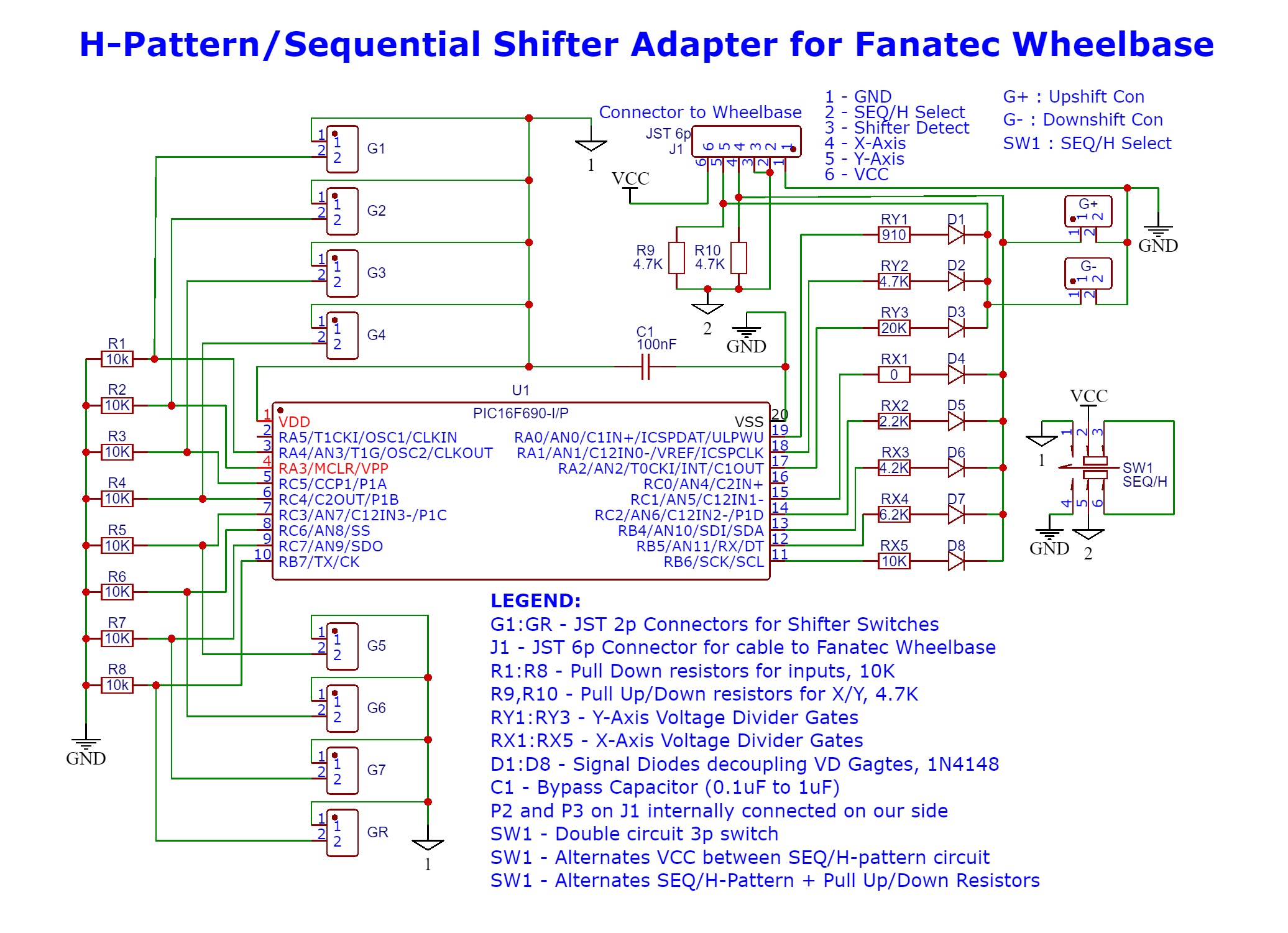
H-Pattern+Sequential Interface Schematics
Please note: this design has not been tested and we cannot confirm it actually works. For now it should be regarded as concept work-in-progress!
The extended design features secondary circuit which allows sequential use on the Shifter 1 port. It is activated by Switch 1. This is dual channel switch. On one channel it switches power to PIC in H-Pattern mode or provides VCC to second channel. On second channel it alternates both Select Pin2 between LOW and HIGH telling the base a H-pattern or Sequential shifter is connected and sets R9 and R10 to PullUp or PullDown state. It has two additional connectors for sequential switches:
Parts List
BOM for both circuits:
| Name | Description | Part | Value | Count |
|---|---|---|---|---|
| G1-G7, GR, G+, G- | Gear Switch Connectors | JST XH 2.54 Plug 2.54mm XH2.54 2Pin | 8 | |
| R1-R8 | PullDown Input Resistors | Metal Film Resistor 0.25W | 10K Ohm | 8 |
| RY1 | Y-Axis Voltage Divider Resistor | Metal Film Resistor 0.25W | 910 Ohm | 1 |
| RY2 | Y-Axis Voltage Divider Resistor | Metal Film Resistor 0.25W | 4.7K Ohm | 1 |
| RY3/td> | Y-Axis Voltage Divider Resistor | Metal Film Resistor 0.25W | 20K Ohm | 2 |
| RX1 | X-Axis Voltage Divider Resistor | Bridged connection, no resistor needed | 10 Ohm | 1 |
| RX2 | X-Axis Voltage Divider Resistor | Metal Film Resistor 0.25W | 2.2K Ohm | 1 |
| RX3 | X-Axis Voltage Divider Resistor | Metal Film Resistor 0.25W | 4.2K Ohm | 1 |
| RX4 | X-Axis Voltage Divider Resistor | Metal Film Resistor 0.25W | 6.2K Ohm | 1 |
| RX5 | X-Axis Voltage Divider Resistor | Metal Film Resistor 0.25W | 10K Ohm | 1 |
| R9, R10 | PullDown Voltage Divider Resistors | Metal Film Resistor 0.25W | 4.7K Ohm | 2 |
| C1 | Bypass Capacitor | Ceramic capacitor 50V | 0.1uF to 1uF | 1 |
| D1-D8 | Decoupling signal diodes | 1N4148 DO-35 IN4148 Switching Diode | 1N4148 | 8 |
| U1 | PIC MicroChip | PIC16F690-I/P DIP-20 Microcontroller | PIC16F690 | 1 |
| U1 | DIP IC Socket | IC Sockets 2.54MM 20P | 20p | 1 |
| SW1 | Switch | Two channel 2 position switch by choice/6p connector | 3x2p | 1 |
| Project Board | Electronic PCB Board 3x7cm Diy Universal Printed Circuit Board | 70x30mm | 1 |
Enclosure files for 3D printer can be obtained HERE
Now that we covered all theory and gathered everything we can proceed to next chapter: Assembly and Conclusion


