Assumptions
- The ClubSport SQ V1.5 is potentiometer based shifter
- It relies on two potentiometers to find the shift level position - vertical and horizontal travel
- Wheelbase has internal calibration mechanism as this measures cannot be always exact
- Wheelbase measures voltage drop on two pins
- Substitution of these resistors with simple voltage divider will fool the base that on the other side is a ClubSport shifter
- Controller will read 8 gear inputs and will switch resistors effectively simulating two voltage dividers connected on X and Y Axis pint to base
- The active logic controller that switches between output will be powered internally with 3.3V from wheelbase
There is no need to delve further in these details as they are very well documented by the Fanashifter project: Fanashifter Project on GitHub. All the reverse-engineering work was already done by B-spec-_-Bob in his project: Conversion of a Logitech shifter for Fanatec wheelbase.
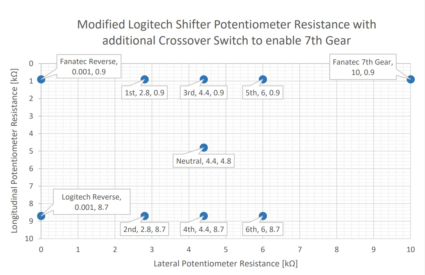
B-spec-_-Bob already measured the ClubSport shifter voltage drops on the two potentiometers and provides calculations for the Potentiometer resistor values at each position in his extensive project documentation.
In the aforementioned guide you will find the following informative graph which depicts what calculated resistance relative values you can expect at each gear position for both potentiometers:
Armed with all this knowledge the idea started to clear up and here is how it goes:
Theory
Pinout
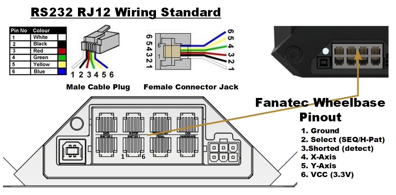
Fanatec wheelbases use the same RJ12 connectors for compatible devices for years. The Shifter2 is great for interfacing sequential shifter as it is internally wired with pull-up resistor and you only have to connect two switches on pin 4 and 5 which pull to Ground once pressed.
For H-pattern shifter we are interested in utilizing the Shifter 1 connector. It supports full feature H-Pattern and Sequential mode shifters. Here is the connector's pinout:
Shifter 1 Pinout
- Pin 1 - Ground
- Pin 2 - Select H-Pattern/Sequential
- Pin 3 - Detect Shifter
- Pin 4 - X-Axis - horizontal positioning potentiometer
- Pin 5 - Y-Axis - vertical positioning potentiometer
- Pin 6 - VCC, +3.3V
Pin operation
- Select (Pin2) - High state (pulled up to VCC) is sequential mode, Low (pulled down to GND) is H-pattern mode.
- Detect (Pin3) - Shorted on shifter side to Pin 2, signals the wheelbase a shifter is connected.
- X-Axis (Pin4) - Voltage drop from shifter indicates at which position is currently the shifter lever. Has 5 discrete states as follows: left most is Reverse, then you have 3 positions for gates 1-2, 3-4, 5-6 and further right is 7th gear. Neutral Gear is in the Middle position - Gate 3-4.
- Y-Axis (Pin5) - Here we have three discrete values indicating UP-Middle-Down shifter position. Neutral is in the middle position again.
Voltage Divider
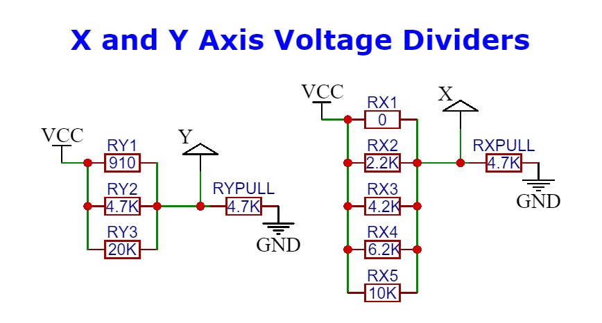
The main idea here is to change potentiometer with voltage dividers. In order to do so we would need to add pull-down resistor in the schematics. As the wheelbase relies on shifter calibration the X-Axis is quite simple to simulate. The Y-Axis on the other hand accept discrete Low-Middle-High values so we need more dramatic voltage drop. This worked pretty well with using the below resistor values:
PIC Microcontroller
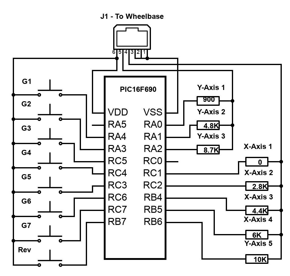
At this point we need something that based on the Gear switches will alternate the output for X and Y Axis. For this we chose PIC16F690 Microchip microcontroller. It has wide operating voltage, fast switching and 17 I/O ports. We need the 20-pin variant.
We will configure 8 I/O ports to act as input and read state of the gear switches. On the other side we will have 8 outputs - 3 for Y and 5 for X Axis. They will alternate based on input and switch between sets of X/Y coordinates. Basic electronics schematics will look something like this (do not attempt to build this one - it will not work!):
Now that we have covered the basics let's dig deeper in next section: Parts, Code, Resources, Schematics


