Why build such adapter? To save a USB port, to go through internal Fanatec Shifter protocol, for easy in-game support and most of all - because we simply can! And yes - this was not tested - but interface should work even on consoles!
The idea here was to build simple logic circuit to interface switch-based shifters to voltage drop output and connect it in the Fanatec wheelbase Shifter 1 port. This allows you to use the internal wheelbase support and is actually quite convenient.
In the current article you can find all needed documentation to build your own.
Main Features
- Uses internal Fanatec Wheelbase Protocol
- Works with any shifter built with switches
- Based on PIC16F690 by Microchip - low voltage, fast response microcontroller
- Works very fast without any delay
- Supported in every game that the standard Fanatec shifter works
- Powered internally by wheelbase - 3.3V
- Not verified - should work on Consoles as well
- Not verified - prototype circuit to accommodate dual H-Pattern/Sequential shifters
This project is inspired by the Fanashifter project: Fanashifter Project on GitHub and the amazing reverse-engineering work done by B-spec-_-Bob: Conversion of a Logitech shifter for Fanatec wheelbase
This is low voltage project without external power yet again you could damage your equipment. Furthermore it was tested only on PC and we can confirm only that compatibility. We do not take responsibility for any injury to yourself or any damage to your equipment. Building this project is at your own risk!
Currently this project does not have commercial variant but we can assist you with providing pre-programmed PICs, partially of full assembled DIY modules. Commercial production is also possible to appear in future.
Let's kick off the Project with the following Video Presentation where you will witness how it operates but also can have a fast crash-course in PIC firmware flashing:
Now that the project's idea is clear we can begin with covering the basics in following section: Assumptions and Theory
Assumptions
- The ClubSport SQ V1.5 is potentiometer based shifter
- It relies on two potentiometers to find the shift level position - vertical and horizontal travel
- Wheelbase has internal calibration mechanism as this measures cannot be always exact
- Wheelbase measures voltage drop on two pins
- Substitution of these resistors with simple voltage divider will fool the base that on the other side is a ClubSport shifter
- Controller will read 8 gear inputs and will switch resistors effectively simulating two voltage dividers connected on X and Y Axis pint to base
- The active logic controller that switches between output will be powered internally with 3.3V from wheelbase
There is no need to delve further in these details as they are very well documented by the Fanashifter project: Fanashifter Project on GitHub. All the reverse-engineering work was already done by B-spec-_-Bob in his project: Conversion of a Logitech shifter for Fanatec wheelbase.
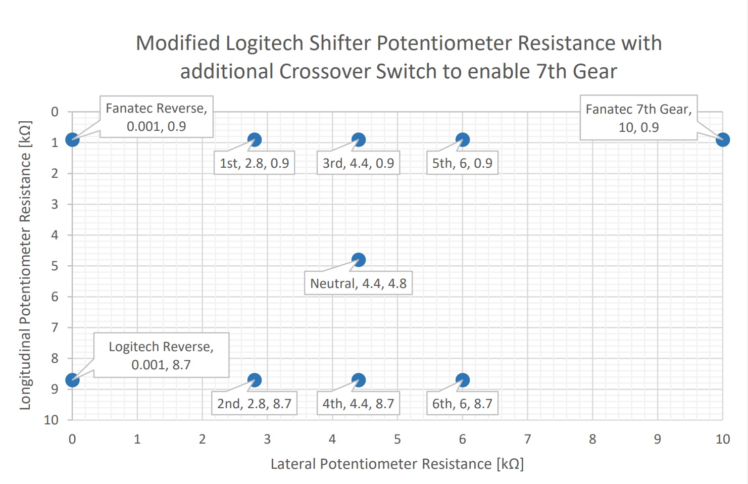
B-spec-_-Bob already measured the ClubSport shifter voltage drops on the two potentiometers and provides calculations for the Potentiometer resistor values at each position in his extensive project documentation.
In the aforementioned guide you will find the following informative graph which depicts what calculated resistance relative values you can expect at each gear position for both potentiometers:
Armed with all this knowledge the idea started to clear up and here is how it goes:
Theory
Pinout
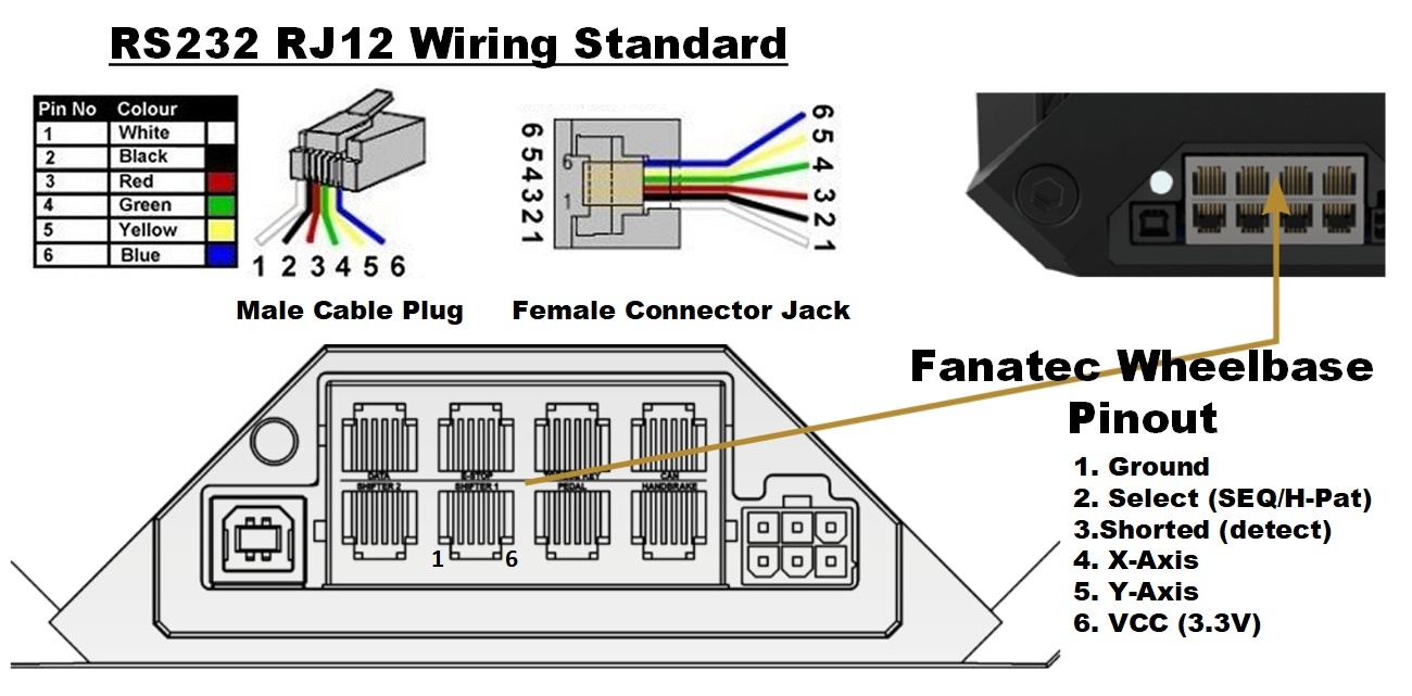
Fanatec wheelbases use the same RJ12 connectors for compatible devices for years. The Shifter2 is great for interfacing sequential shifter as it is internally wired with pull-up resistor and you only have to connect two switches on pin 4 and 5 which pull to Ground once pressed.
For H-pattern shifter we are interested in utilizing the Shifter 1 connector. It supports full feature H-Pattern and Sequential mode shifters. Here is the connector's pinout:
Shifter 1 Pinout
- Pin 1 - Ground
- Pin 2 - Select H-Pattern/Sequential
- Pin 3 - Detect Shifter
- Pin 4 - X-Axis - horizontal positioning potentiometer
- Pin 5 - Y-Axis - vertical positioning potentiometer
- Pin 6 - VCC, +3.3V
Pin operation
- Select (Pin2) - High state (pulled up to VCC) is sequential mode, Low (pulled down to GND) is H-pattern mode.
- Detect (Pin3) - Shorted on shifter side to Pin 2, signals the wheelbase a shifter is connected.
- X-Axis (Pin4) - Voltage drop from shifter indicates at which position is currently the shifter lever. Has 5 discrete states as follows: left most is Reverse, then you have 3 positions for gates 1-2, 3-4, 5-6 and further right is 7th gear. Neutral Gear is in the Middle position - Gate 3-4.
- Y-Axis (Pin5) - Here we have three discrete values indicating UP-Middle-Down shifter position. Neutral is in the middle position again.
Voltage Divider
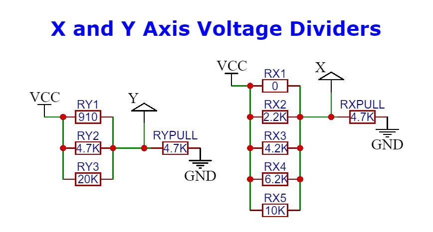
The main idea here is to change potentiometer with voltage dividers. In order to do so we would need to add pull-down resistor in the schematics. As the wheelbase relies on shifter calibration the X-Axis is quite simple to simulate. The Y-Axis on the other hand accept discrete Low-Middle-High values so we need more dramatic voltage drop. This worked pretty well with using the below resistor values:
PIC Microcontroller
At this point we need something that based on the Gear switches will alternate the output for X and Y Axis. For this we chose PIC16F690 Microchip microcontroller. It has wide operating voltage, fast switching and 17 I/O ports. We need the 20-pin variant.
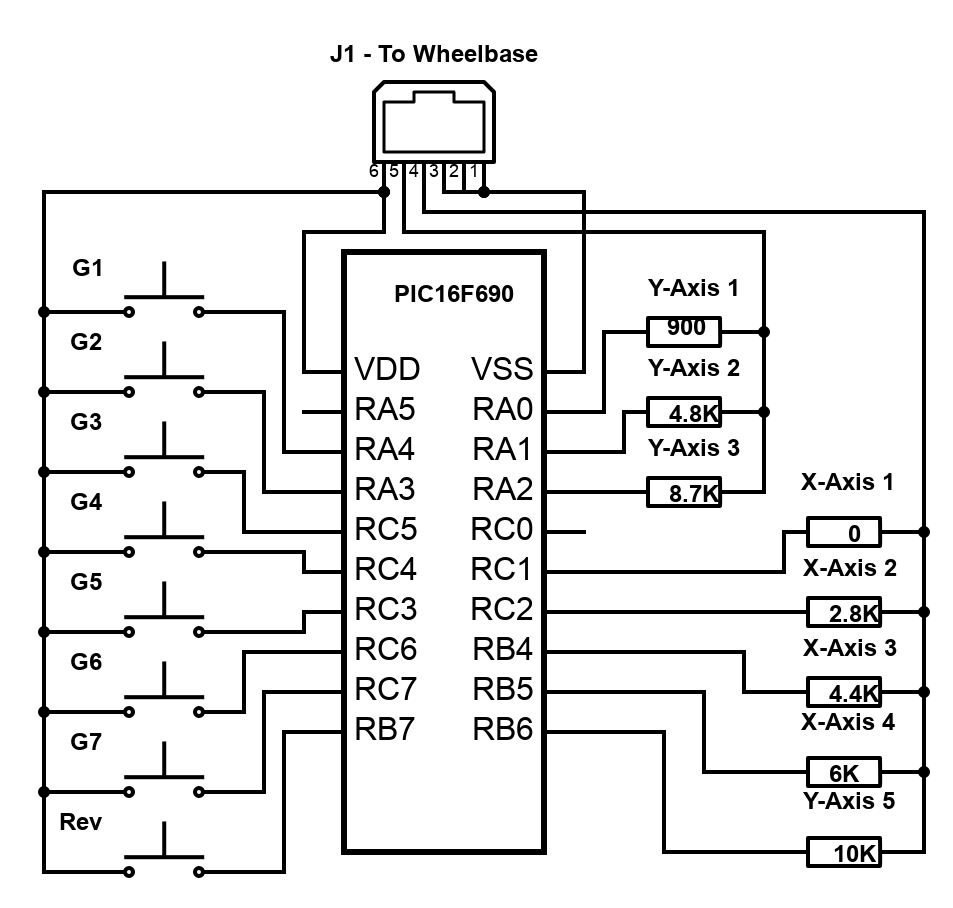
We will configure 8 I/O ports to act as input and read state of the gear switches. On the other side we will have 8 outputs - 3 for Y and 5 for X Axis. They will alternate based on input and switch between sets of X/Y coordinates. Basic electronics schematics will look something like this (do not attempt to build this one - it will not work!):
Now that we have covered the basics let's dig deeper in next section: Parts, Code, Resources, Schematics
Resources
This is advanced DIY project and you will need some PIC programming understanding, specific tools (PIC programmer) and decent soldering skills. Here is what you will need:
- The HEX code from GitHub project page
- PIC Programmer - K150 clone works well
- MicroPro PIC programming software
- PIC flashing knowledge, following links will help:
- Program a PIC 16F690 with the DIY Kit 150 Programmer
- How to Use K150 PIC Programmer Video
- K150 USB PIC Programmer
- K150 USB PIC Programmer Manual
- STLs for open-top mount bracket and full enclosure for 3D Print
Program Code
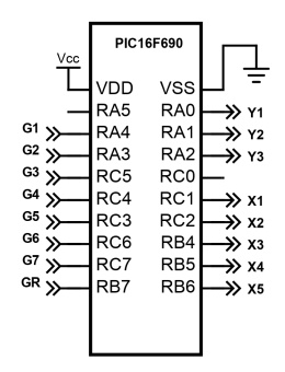
Source prgram code and compiled HEX file for flashing can be found on the Project GitHub Page. Program is very simple, tracks 8 inputs connected to the Shifter Gear Switches and alternates amongst 8 outputs which simulate X and Y Axis Voltage Drops. Gear states are as follows:
- X-Axis has 5 discreet states determining horizontal stick position: Low (R) - Low-Med (1-2) - Medium (3-4) - Med-High (5-6) - High (7).
- Y-Axis has 3 discreet states determining vertical stick position: Low (stick is Up) - Medium (Neutral) - High (stick is Down).
- Neutral - X is Medium, Y is Medium. Program keeps Y2 and X3 outputs engaged when no input is detected.
- 1st Gear - X is Low-Med, Y is Low. Outputs X2 and Y1 are engaged.
- 2nd Gear - X is Low-Med, Y is High. Outputs X2 and Y3 are engaged.
- 3rd Gear - X is Medium, Y is Low. Outputs X3 and Y1 are engaged.
- 4th Gear - X is Medium, Y is High. Outputs X3 and Y3 are engaged.
- 5th Gear - X is Med-High, Y is Low. Outputs X4 and Y1 are engaged.
- 6th Gear - X is Med-High, Y is High. Outputs X4 and Y3 are engaged.
- 7th Gear - X is High, Y is Low. Outputs X5 and Y1 are engaged.
- Reverse Gear - X is Low, Y is Low. Outputs X1 and Y1 are engaged.
Below is the source code and simplified I/O digram displaying how the PIC16F690 gates are configured:
Flashing Firmware
After you install the MicoPro software and downloaded the HEX file it is simple matter of connecting you PIC programmer and flash it to your PIC16F690 microchip. The software will show you the correct position of the PIC in the ZIF (Zero Insertion Force) socket. You will notice that it supports only 14pin PIC16F690s. This is not an issue - you can just bend the bottom most four pins and still place it properly and be able to flash the firmware successfully.
H-Pattern Interface Schematics
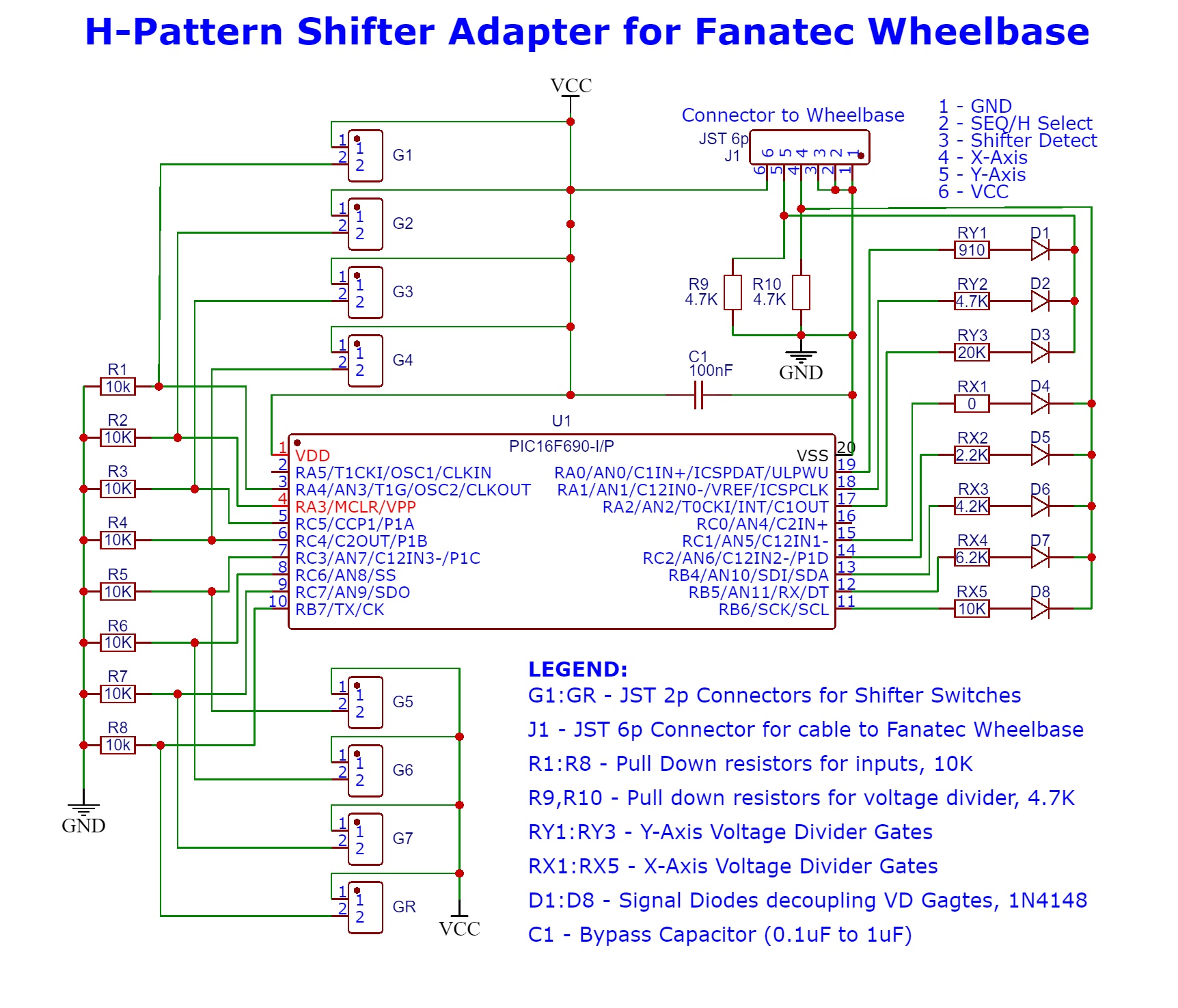
All Gear Inputs are pulled down to LOW (GND) and upon switch engaged they are pulled up to HIGH (VCC). Wheelbase X-Axis and Y-Axis pins are pulled down to LOW and upon output from PIC the Voltage Divider circuit is engaged, voltage drop is present on X and Y pins. All outputs are decoupled with Diodes so no feedback is present on PIC I/O pins:
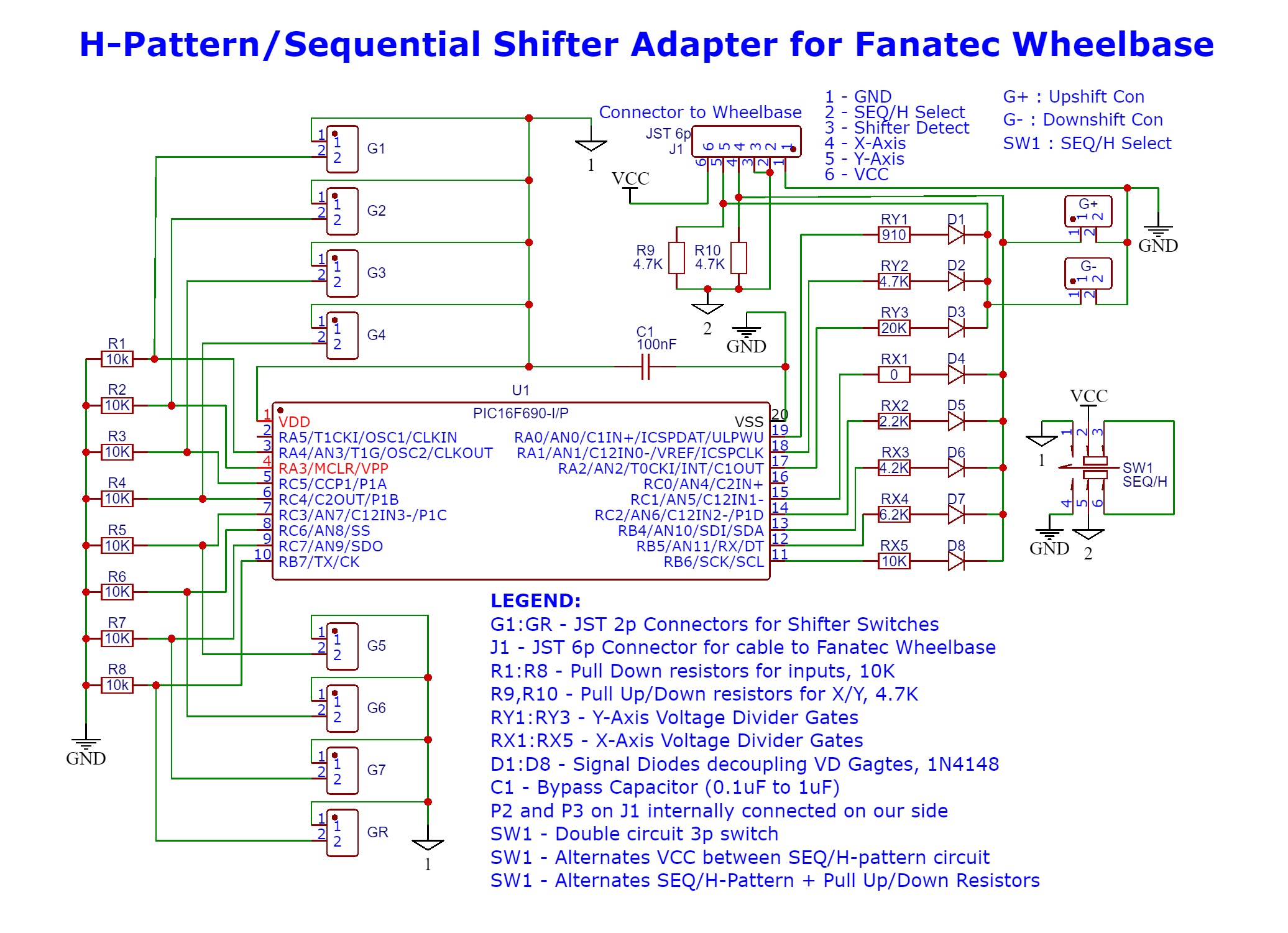
H-Pattern+Sequential Interface Schematics
Please note: this design has not been tested and we cannot confirm it actually works. For now it should be regarded as concept work-in-progress!
The extended design features secondary circuit which allows sequential use on the Shifter 1 port. It is activated by Switch 1. This is dual channel switch. On one channel it switches power to PIC in H-Pattern mode or provides VCC to second channel. On second channel it alternates both Select Pin2 between LOW and HIGH telling the base a H-pattern or Sequential shifter is connected and sets R9 and R10 to PullUp or PullDown state. It has two additional connectors for sequential switches:
Parts List
BOM for both circuits:
| Name | Description | Part | Value | Count |
|---|---|---|---|---|
| G1-G7, GR, G+, G- | Gear Switch Connectors | JST XH 2.54 Plug 2.54mm XH2.54 2Pin | 8 | |
| R1-R8 | PullDown Input Resistors | Metal Film Resistor 0.25W | 10K Ohm | 8 |
| RY1 | Y-Axis Voltage Divider Resistor | Metal Film Resistor 0.25W | 910 Ohm | 1 |
| RY2 | Y-Axis Voltage Divider Resistor | Metal Film Resistor 0.25W | 4.7K Ohm | 1 |
| RY3/td> | Y-Axis Voltage Divider Resistor | Metal Film Resistor 0.25W | 20K Ohm | 2 |
| RX1 | X-Axis Voltage Divider Resistor | Bridged connection, no resistor needed | 10 Ohm | 1 |
| RX2 | X-Axis Voltage Divider Resistor | Metal Film Resistor 0.25W | 2.2K Ohm | 1 |
| RX3 | X-Axis Voltage Divider Resistor | Metal Film Resistor 0.25W | 4.2K Ohm | 1 |
| RX4 | X-Axis Voltage Divider Resistor | Metal Film Resistor 0.25W | 6.2K Ohm | 1 |
| RX5 | X-Axis Voltage Divider Resistor | Metal Film Resistor 0.25W | 10K Ohm | 1 |
| R9, R10 | PullDown Voltage Divider Resistors | Metal Film Resistor 0.25W | 4.7K Ohm | 2 |
| C1 | Bypass Capacitor | Ceramic capacitor 50V | 0.1uF to 1uF | 1 |
| D1-D8 | Decoupling signal diodes | 1N4148 DO-35 IN4148 Switching Diode | 1N4148 | 8 |
| U1 | PIC MicroChip | PIC16F690-I/P DIP-20 Microcontroller | PIC16F690 | 1 |
| U1 | DIP IC Socket | IC Sockets 2.54MM 20P | 20p | 1 |
| SW1 | Switch | Two channel 2 position switch by choice/6p connector | 3x2p | 1 |
| Project Board | Electronic PCB Board 3x7cm Diy Universal Printed Circuit Board | 70x30mm | 1 |
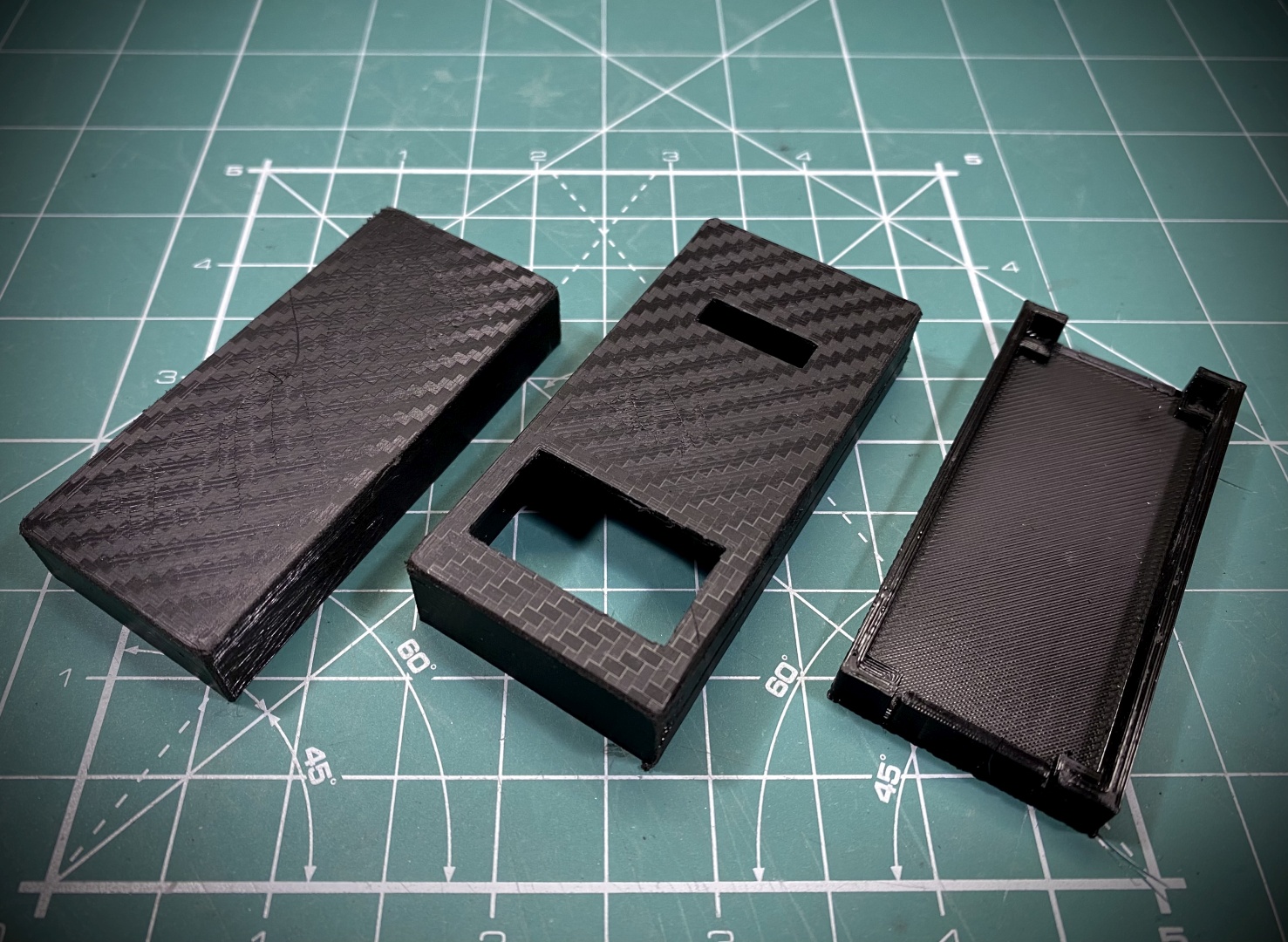
Enclosure files for 3D printer can be obtained HERE
Now that we covered all theory and gathered everything we can proceed to next chapter: Assembly and Conclusion
Parts List
PCB Assembly
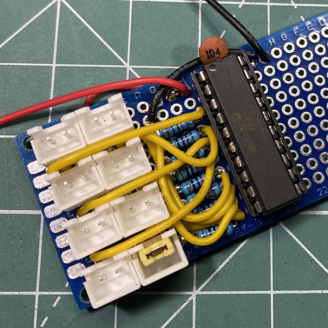
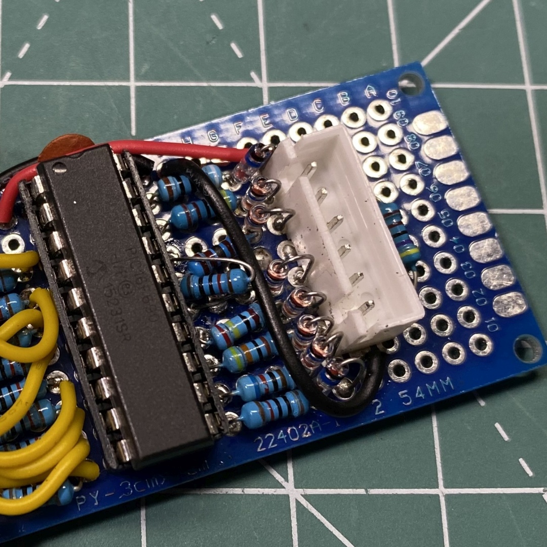
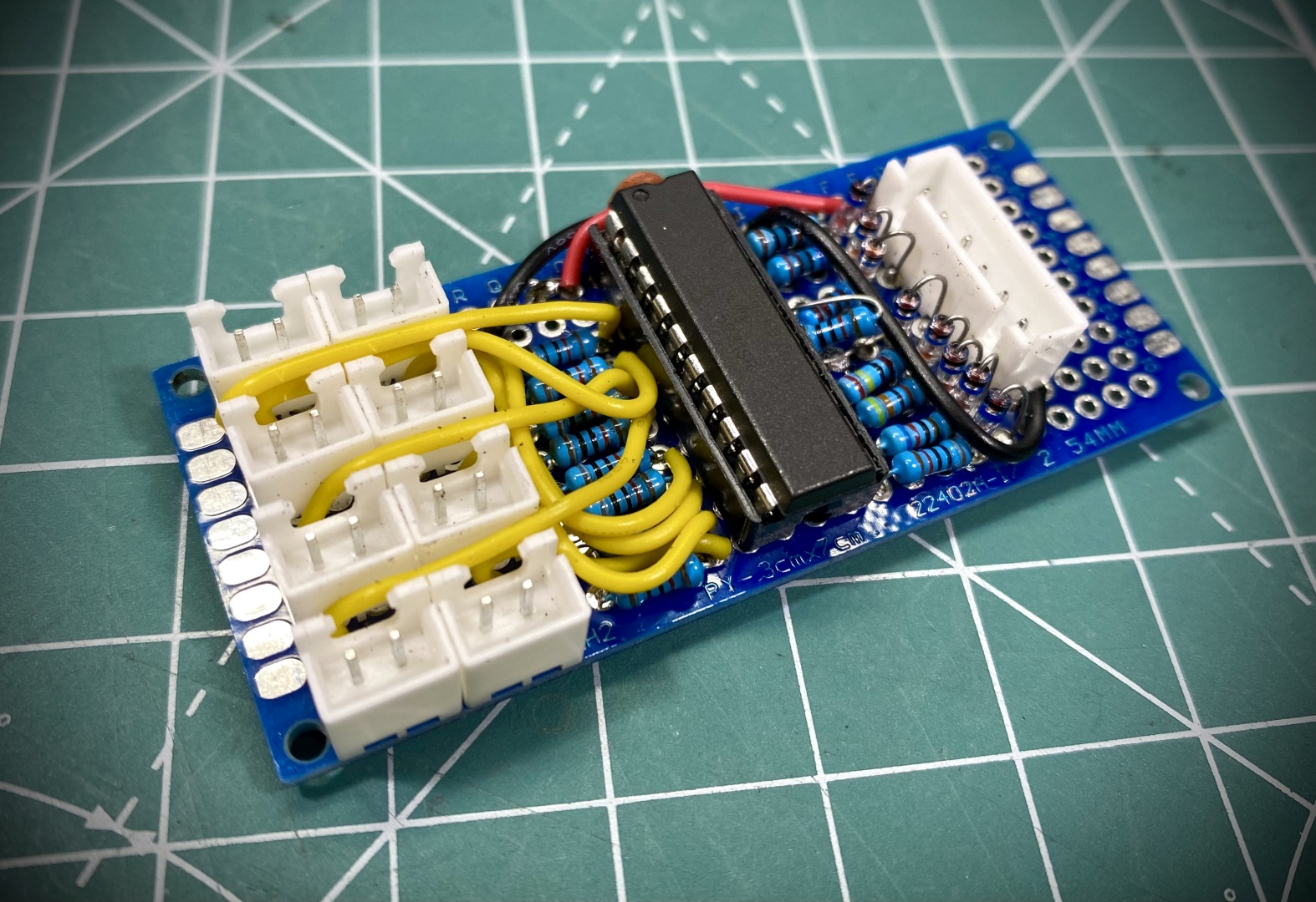
The basic design is actually simple to be soldered to a 70x30mm project PCB. The DIP socket goes in the center of it providing enough space to put on the left side the input switch connectors and on the right side a 6pin JST connector + voltage divider to wheelbase:
As you can see on above pictures it is straightforward to solder the PullDown R1-8 resistors right next to socket and next to them align 2 columns by 4 connectors for the shifter Gear switches. They are connected to VCC on one side and on the other with solder bridges to the PIC's inputs.
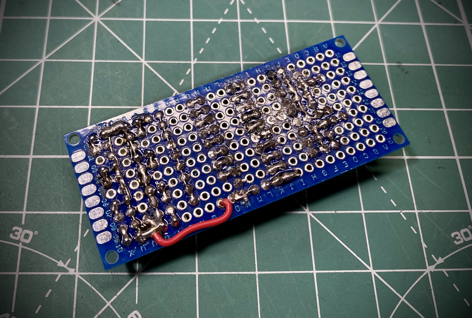
On the right side we have the outputs which are directly connected to the Voltage Divider resistors followed by the signal diodes. On Y3 output we have two resistors as we did not have 20KOhm one, on X1 we have a simple wire bridge. All 3 Y diodes combine in one output and connect on pin 5 (Y-Axis), all 5 X outputs do respectively the same to Pin 4 (X-Axis). PullDowns are connected on the right of the 6p connector. Bypass capacitor is soldered right next to the PIC threaded below the DIP socket.
Final circuit should look something like that - as you can see there are not a lot of bridges and is very simple even with project PCB:
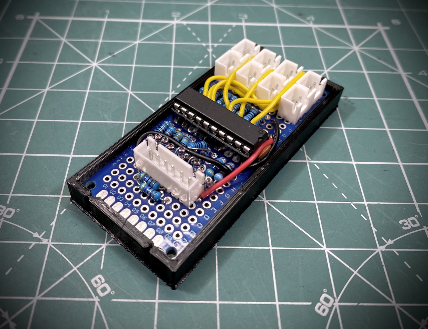
You can download HERE designs for open-top bracket or full covered enclosure for this project:
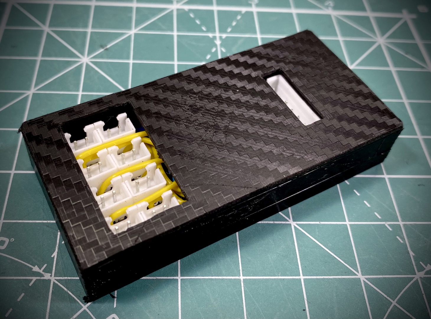
And at the end - this is the finished product:
Now comes the fun part - connecting our interface adapter to a H-Pattern shifter. Our obvious choice is the BDH H1 Bazooka shifter, for which you can read our impressions in This Long Term Review. As you can see from the pictures below the Interface Adapter even with full enclosure has smaller footprint than a standard USB gamepad adapter:
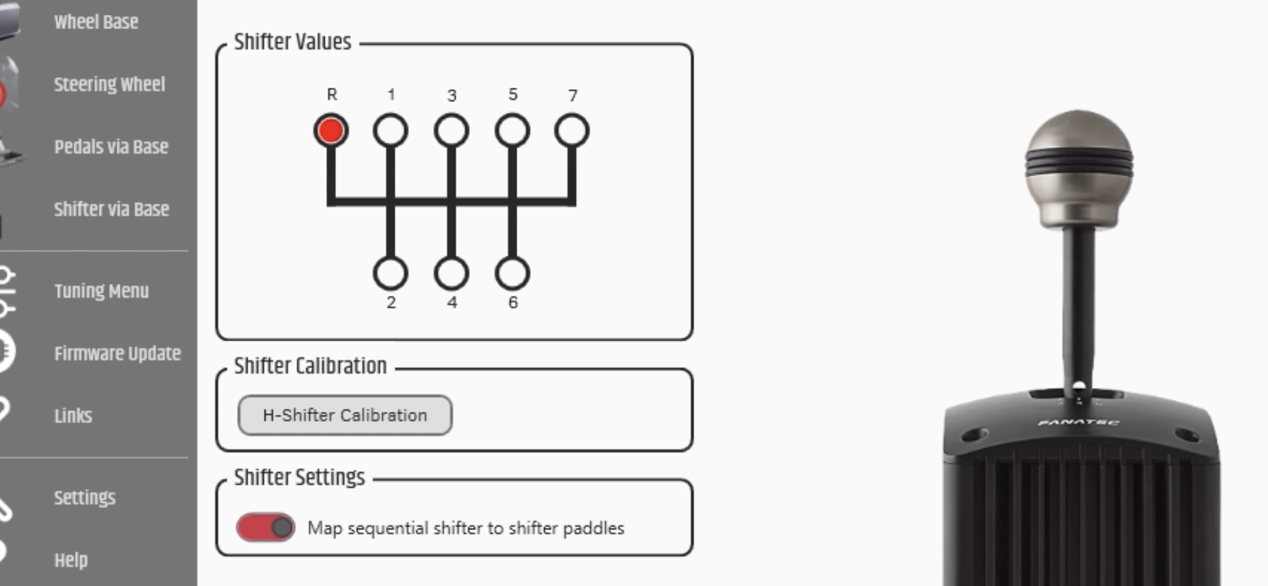
If you managed to complete everything properly after connecting you newly interfaced shifter to Fanatec wheelbase and having performed initial calibration you hopefully will get the following satisfying screen:
Congratulations! Now you have natively supported non-Fanatec shifter working with the internal protocol seamlessly with your wheelbase. We are pretty sure that you will be able even to use it on Consoles!
Conclusion
This is fun little low cost project that will allow you to bring a aftermarket H-Pattern on Sequential shifter to your Fanatec ecosystem. It works reliable, has real-time response and utilizes the internal Wheelbase protocol. This we realize it is not particularly tempting for PC users but still having one less device to bother with in-game configuration and one more free USB is not a bad thing. For console users on the other side - this is welcome addition opening possibilities to use wide array of very cool shifters present out there on the market.
In either case we hope you enjoyed the report for this project and will have great fun building your own Universal Interface Adapter!

